Nissan Rogue. Manual - part 778
HAC-134
< ECU DIAGNOSIS INFORMATION >
[MANUAL AIR CONDITIONING]
FRONT AIR CONTROL
17
(W)
19
(B)
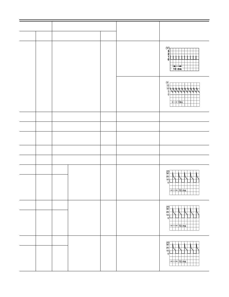
Blower fan ON signal
Output
• Ignition switch ON
• Blower motor: OFF
• Ignition switch ON
• Blower motor: ON
18
(BR)
19
(B)
Sensor ground
—
Ignition switch ON
0 – 0.1 V
19
(B)
Ground
Ground
—
Ignition switch ON
0 – 0.1 V
21
(BG)
19
(B)
Intake sensor signal
Input
Ignition switch ON
0 – 4.8 V
Output voltage varies with evapo-
rator fin temperature
23
(R)
19
(B)
CAN-L
Input/
Output
Ignition switch ON
—
24
(SB)
19
(B)
ACTR V
Output
Ignition switch ON
Battery voltage
25
(GR)
19
(B)
A/MIX
drive 3
Air mix door motor
(passenger side)
drive signal
Output
• Ignition switch ON
• Right after the tempera-
ture control switch (pas-
senger side) operation
26
(BR)
19
(B)
A/MIX
drive 4
27
(LG)
19
(B)
INTAKE
drive 3
Intake door motor
drive signal
Output
• Ignition switch ON
• Right after the intake
switch operation
28
(W)
19
(B)
INTAKE
drive 4
29
(BG)
19
(B)
MODE
drive 3
Mode door motor
drive signal
Output
• Ignition switch ON
• Right after the MODE
switch operation
30
(G)
19
(B)
MODE
drive 4
Terminal No.
(Wire color)
Description
Condition
Value
+
−
Signal name
Input/
Output
JMIIA0941GB
PKIB4960J
JPIIA1647GB
JPIIA1647GB
JPIIA1647GB