Nissan Rogue. Manual - part 744


  Index      Nissan     Nissan Rogue (2015 year) - Service and Repair Manual


Search            


Content   ..  742  743  744  745   ..


Nissan Rogue. Manual - part 744


HA-44

< REMOVAL AND INSTALLATION >

HEATING AND COOLING UNIT ASSEMBLY

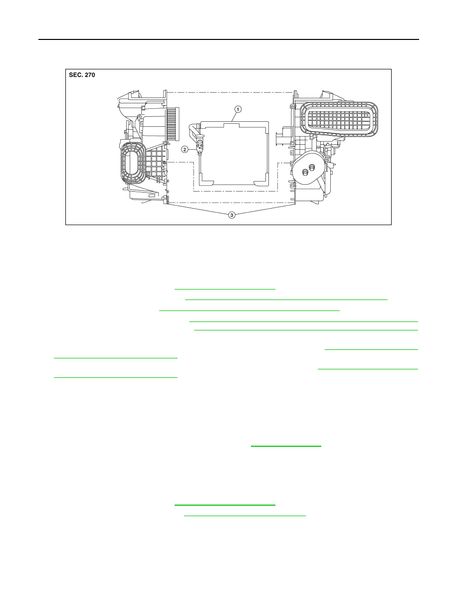
EVAPORATOR : Exploded View

INFOID:0000000011279506

EVAPORATOR : Removal and Installation

INFOID:0000000011279507

REMOVAL

1. Discharge the refrigerant. Refer to 

HA-22, "Recycle Refrigerant"

.

2. Remove front foot duct (LH). Refer to 

VTL-10, "FRONT FOOT DUCT : Removal and Installation"

.

3. Remove heater core. Refer to 

HA-43, "HEATER CORE : Removal and Installation"

.

4. Remove intake door motor. Refer to 

HAC-110, "INTAKE DOOR MOTOR : Removal and Installation"

(AUTOMATIC AIR CONDITIONING) or 

HAC-186, "INTAKE DOOR MOTOR : Removal and Installation"

(MANUAL AIR CONDITIONING).

5. Remove air mix door motor (LH) (AUTOMATIC AIR CONDITONING). Refer to 

HAC-110, "AIR MIX DOOR

MOTOR : Removal and Installation"

.

6. Remove air mix door motor (MANUAL AIR CONDITIONING). Refer to 

HAC-186, "AIR MIX DOOR

MOTOR : Removal and Installation"

.

7. Separate the heating and cooling unit assembly and remove evaporator.

INSTALLATION

Installation is in the reverse order of removal.

CAUTION:

• Do not reuse O-rings.

• Apply A/C oil to new O-rings for installation.

• After charging the refrigerant, check for leaks. Refer to 

HA-21, "Leak Test"

.

EXPANSION VALVE
EXPANSION VALVE : Removal and Installation

INFOID:0000000011279508

REMOVAL

1. Discharge the refrigerant. Refer to 

HA-22, "Recycle Refrigerant"

.

2. Remove cowl top extension. Refer to 

EXT-25, "Removal and Installation"

.

1.

Evaporator

2.

Expansion valve

3.

Heating and cooling unit assembly

ALIIA0945ZZ

HEATING AND COOLING UNIT ASSEMBLY

HA-45

< REMOVAL AND INSTALLATION >

C

D

E

F

G

H

J

K

L

M

A

B

HA

N

O

P

3. Remove the bolt (A) that retains the low-pressure pipe and high-

pressure pipe to the expansion valve (1).

CAUTION:

Cap or wrap the joint of the pipe with suitable material such

as vinyl tape to avoid the entry of air.

4. Remove bolts (A) and expansion valve (1).

INSTALLATION

Installation is in the reverse order of removal.

CAUTION:

• Tighten bolts to specification. Refer to 

HA-31, "Exploded View"

.

• Do not reuse O-rings.

• Apply A/C oil to new O-rings for installation.

• After charging refrigerant, check for leaks. Refer to 

HA-21, "Leak Test"

.

ALIIA0935ZZ

ALIIA0948ZZ

HA-46

< SERVICE DATA AND SPECIFICATIONS (SDS) 

SERVICE DATA AND SPECIFICATIONS (SDS)

SERVICE DATA AND SPECIFICATIONS (SDS)

SERVICE DATA AND SPECIFICATIONS (SDS)

Compressor

INFOID:0000000011279509

Oil

INFOID:0000000011279510

Refrigerant

INFOID:0000000011279511

Model

DENSO

Type

Variable displacement swash plate

Displacement

140.6 cm

3

 (8.6 cu in)/rev

Number of cylinders

6

Cylinder bore diameter x stroke
mm (in)

32 x 29.1 mm (1.3 x 1.1 in)

Direction of rotation

Clockwise (viewed from clutch)

Drive belt

Poly V 6 grooves

Disc to pulley clearance

Standard

0.21 – 0.55 mm (0.008 – 0.022 in)

Name

ND-OIL8

Capacity
m  (US fl oz, lmp fl oz)

Total in system

110 (3.7, 3.9)

Compressor (service part) charging 
amount

Refer to 

HA-25, "Oil Adjusting Procedure for 

Compressor Replacement"

.

Type

HFC-134a (R-134a)

Capacity

0.50 kg (1.10 lbs)

HAC-1

VENTILATION, HEATER & AIR CONDITIONER

C

D

E

F

G

H

J

K

L

M

SECTION 

HAC

A

B

HAC

N

O

P

CONTENTS

HEATER & AIR CONDITIONING CONTROL SYSTEM

AUTOMATIC AIR CONDITIONING

PRECAUTION ...............................................

5

PRECAUTIONS ...................................................

5

Precaution for Supplemental Restraint System 
(SRS) "AIR BAG" and "SEAT BELT PRE-TEN-
SIONER" .................................................................
..

5

Precaution for Work  ..................................................

5

PREPARATION ............................................

6

PREPARATION ...................................................

6

Special Service Tool  .................................................

6

Commercial Service Tool  ..........................................

6

SYSTEM DESCRIPTION  ..............................

7

COMPONENT PARTS  ........................................

7

Component Part Location  .........................................

7

SYSTEM .............................................................

10

System Description  .................................................

10

Air Flow Control .......................................................

11

Air Inlet Control  .......................................................

12

Air Outlet Control .....................................................

13

Compressor Control  ................................................

13

Door Control ............................................................

13

Temperature Control  ...............................................

18

Fail-safe ..................................................................

18

OPERATION .......................................................

19

Switch Name and Function  .....................................

19

DIAGNOSIS SYSTEM (A/C AUTO AMP.)  .........

22

Description ..............................................................

22

CONSULT Function (HVAC) ...................................

22

DIAGNOSIS SYSTEM (IPDM E/R) .....................

26

CONSULT Function (IPDM E/R) .............................

26

ECU DIAGNOSIS INFORMATION  ..............

29

A/C AUTO AMP.  ...............................................

29

Reference Value ......................................................

29

Fail-safe ...................................................................

32

DTC Inspection Priority Chart ...............................

32

DTC Index  ...............................................................

33

ECM, IPDM E/R, BCM .......................................

34

List of ECU Reference .............................................

34

WIRING DIAGRAM ......................................

35

AUTOMATIC AIR CONDITIONING SYSTEM ...

35

Wiring Diagram ........................................................

35

BASIC INSPECTION  ...................................

46

DIAGNOSIS AND REPAIR WORKFLOW  ........

46

Work Flow ................................................................

46

OPERATION INSPECTION  ..............................

48

Work Procedure .......................................................

48

SYSTEM SETTING ...........................................

50

Temperature Setting Trimmer  .................................

50

Foot Position Setting Trimmer  .................................

50

Inlet Port Memory Function (FRE) ...........................

50

Inlet Port Memory Function (REC)  ..........................

51

Target Evaporator Temp Upper Limit  ......................

51

DOOR MOTOR STARTING POSITION RE-
SET ....................................................................

52

Description ...............................................................

52

Work Procedure .......................................................

52

DTC/CIRCUIT DIAGNOSIS  .........................

53

U1000 CAN COMM CIRCUIT  ...........................

53

Description ...............................................................

53

DTC Logic ................................................................

53

Diagnosis Procedure  ...............................................

53

U1010 CONTROL UNIT (CAN) .........................

54

Description ...............................................................

54


Content   ..  742  743  744  745   ..