Nissan Rogue. Manual - part 650
HAZARD SWITCH
EXL-229
< DTC/CIRCUIT DIAGNOSIS >
[LED HEADLAMP]
C
D
E
F
G
H
I
J
K
M
A
B
EXL
N
O
P
HAZARD SWITCH
Component Function Check
INFOID:0000000011421504
1.
CHECK HAZARD SWITCH SIGNAL BY CONSULT
CONSULT DATA MONITOR
1. Turn ignition switch ON.
2. Select “HAZARD SW” in “Data Monitor” of “BCM (FLASHER)”.
3. With operating the hazard switch, check the monitor status.
Is the inspection result normal?
YES
>> Hazard switch circuit is normal.
NO
>> Refer to
EXL-229, "Diagnosis Procedure"
.
Diagnosis Procedure
INFOID:0000000011421505
1.
CHECK HAZARD SWITCH SIGNAL INPUT
1. Turn ignition switch OFF.
2. Disconnect hazard switch connector.
3. Check voltage between hazard switch connector and ground.
Is the inspection result normal?
YES
>> GO TO 4.
NO
>> GO TO 2.
2.
CHECK HAZARD SWITCH SIGNAL OPEN CIRCUIT
1. Disconnect BCM connector.
2. Check continuity between hazard switch harness connector and BCM harness connector.
Is the inspection result normal?
YES
>> GO TO 3.
NO
>> Repair or replace harness.
3.
CHECK HAZARD SWITCH SIGNAL SHORT CIRCUIT
Check continuity between hazard switch harness connector and ground.
Is the inspection result normal?
YES
>> Replace BCM. Refer to
BCS-75, "Removal and Installation"
(with Intelligent Key system) or
135, "Removal and Installation"
(without Intelligent Key system).
NO
>> Repair or replace harness.
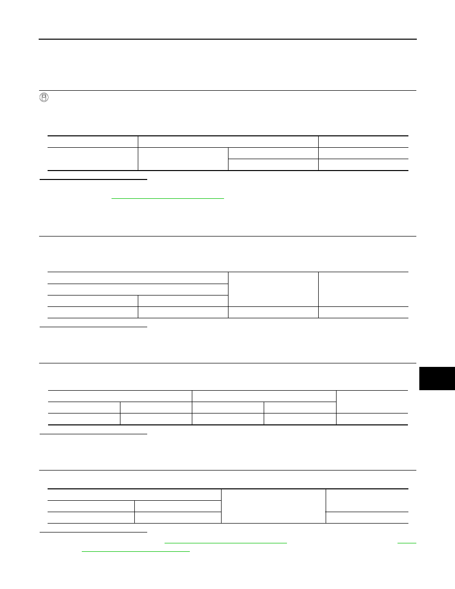
Monitor item
Condition
Monitor status
HAZARD SW
Hazard switch
ON
On
OFF
Off
(+)
(
−)
Voltage (Approx.)
Hazard switch
Connector
Terminal
M26
2
Ground
Battery voltage
Hazard switch
BCM
Continuity
Connector
Terminal
Connector
Terminal
M26
2
M18
11
Yes
Hazard switch
Ground
Continuity
Connector
Terminal
M26
2
No