Nissan Rogue. Manual - part 578


  Index      Nissan     Nissan Rogue (2015 year) - Service and Repair Manual


Search            


Content   ..  576  577  578  579   ..


Nissan Rogue. Manual - part 578


CAMSHAFT

EM-77

< REMOVAL AND INSTALLATION >

C

D

E

F

G

H

I

J

K

L

M

A

EM

N

P

O

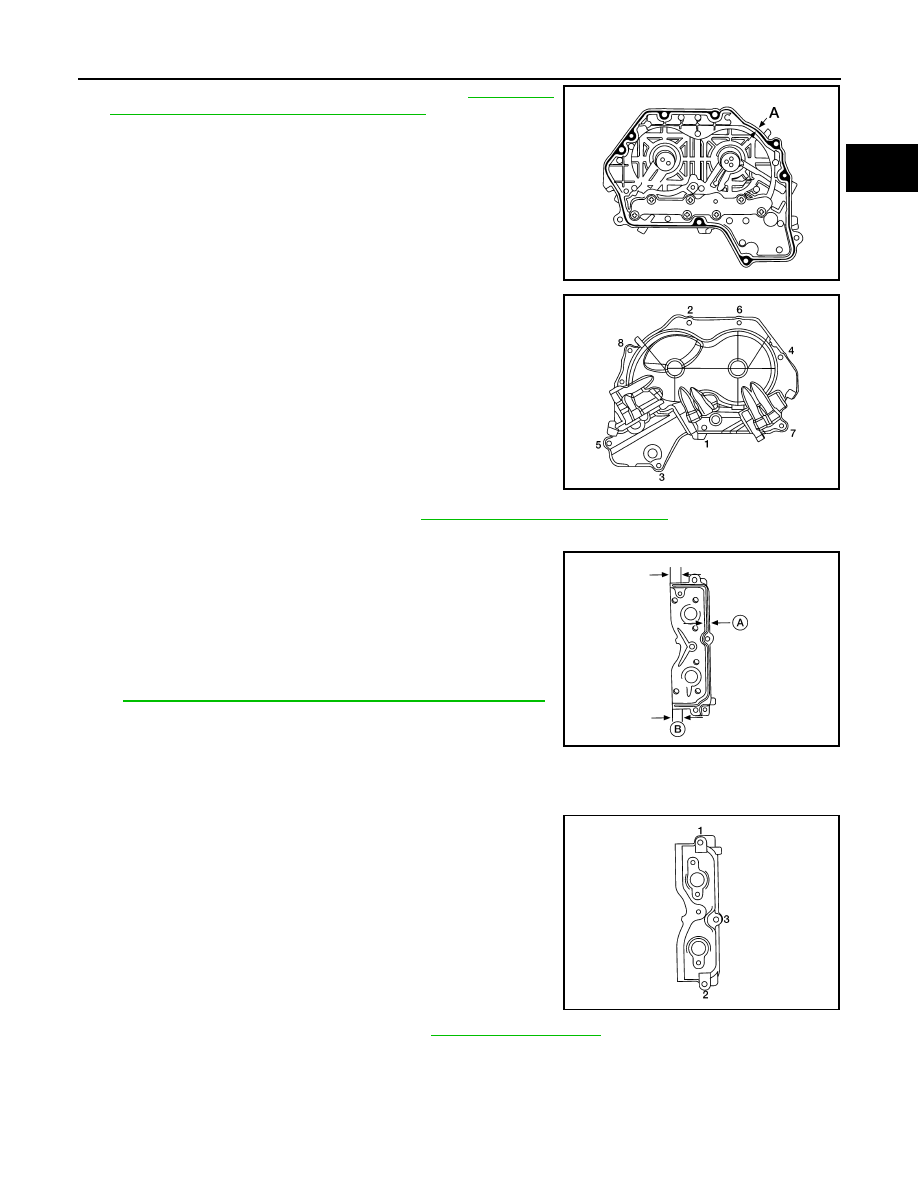
c. Apply liquid gasket to the positions shown. Refer to 

GI-22, "Rec-

ommended Chemical Products and Sealants"

.

d. Install valve timing control cover.

• Tighten the bolts to specification in the numerical order as

shown.

9. Check and adjust valve clearances. Refer to 

EM-21, "Camshaft valve clearance"

.

10. Install camshaft position sensor bracket.
a. Apply liquid gasket to camshaft position sensor bracket as

shown. 

CAUTION:

• Use Genuine Silicone RTV Sealant, or equivalent. Refer to

GI-22, "Recommended Chemical Products and Sealants"

.

• After installation be sure to wipe off excessive liquid gas-

ket leaking from part (B).

• Installation should be done within 5 minutes after apply-

ing liquid gasket.

• Do not fill the engine with engine oil for at least 30 minutes after the components are installed to

allow the liquid gasket to cure.

b. Tighten bolts to specification in numerical order shown. 

11. Install the camshaft position sensors. Refer to 

EM-69, "Exploded View"

.

12. Installation of the remaining components is in the reverse order of removal.

Inspection After Installation

INFOID:0000000011279968

Inspection of Camshaft Sprocket (INT) Oil Groove and Camshaft Sprocket (EXH) Oil Groove

Diameter (A)

: 3.4 - 4.4 mm (0.134 - 0.173 in)

AWBIA1362ZZ

ALBIA0839GB

(A) : 2.0 - 3.0 mm (0.079-0.118)
(B) : 10.5 mm (0.413 in)

Camshaft position 
sensor bracket bolts

: 10.41 N·m (1.1 kg-m, 8 ft-lb)

ALBIA0907GB

ALBIA0908GB

EM-78

< REMOVAL AND INSTALLATION >

CAMSHAFT

WARNING:

Check when engine is cold so as to prevent burns from any splashing engine oil.

CAUTION:

Perform this inspection only when DTC P0011, P0014, P052A, P052B is detected in self-diagnostic

results of CONSULT and it is directed according to inspection procedure of EC section. 
1. Check engine oil level and adjust oil level as necessary. Refer to 

LU-7, "Inspection"

.

2. Remove the intake valve timing intermediate lock control solenoid valve, intake valve timing control sole-

noid valve, and exhaust valve timing control solenoid valve. Refer to 

EM-79, "Intake Valve Timing Interme-

diate Lock Control Solenoid Valve, Intake Valve Timing Control Solenoid Valve, and Exhaust Valve Timing

Control Solenoid Valve"

.

3. Perform the following procedure to prevent the engine from being unintentionally started while checking.
a. Release fuel pressure. Refer to 

EC-147, "Work Procedure"

.

b. Disconnect injector harness connectors.
4. Crank engine, and then make sure that engine oil comes out of

the valve timing control cover oil holes (A). End cranking after

checking.

WARNING:

Be careful not to touch rotating parts (drive belt, crankshaft

pulley, etc.).

CAUTION:

• Engine oil may squirt from intake valve timing intermedi-

ate lock control solenoid valve, intake valve timing control

solenoid valve, exhaust valve timing control solenoid

valve installation holes during cranking. Use a shop cloth

to prevent engine oil from splashing on worker, engine

components and vehicle. 

• Do not allow engine oil to get on rubber components such as drive belts or engine mount insula-

tors. Immediately wipe off any splashed engine oil.

5. If engine oil does not come out from valve timing control cover oil holes (A), diagnose problem in lubrica-

tion circuit such as dirty oil groove between oil strainer and intake valve timing intermediate lock control

solenoid valve, intake valve timing control solenoid valve, or exhaust valve timing control solenoid valve.

Refer to 

LU-5, "Engine Lubrication System"

.

a. Remove components between intake valve timing intermediate lock control solenoid valve, intake valve

timing control solenoid valve, exhaust valve timing control solenoid valve and camshaft sprocket (INT) or

camshaft sprocket (EXH), (if necessary) and then check each oil groove for clogging.

b. Clean oil groove if necessary. Refer to 

LU-5, "Engine Lubrication System"

.

6. After inspection, install the remaining components in the reverse order of removal.

ALBIA0909GB

VALVE TIMING CONTROL

EM-79

< REMOVAL AND INSTALLATION >

C

D

E

F

G

H

I

J

K

L

M

A

EM

N

P

O

VALVE TIMING CONTROL

Exploded View

INFOID:0000000011279969

Intake Valve Timing Intermediate Lock Control Solenoid Valve, Intake Valve Timing 
Control Solenoid Valve, and Exhaust Valve Timing Control Solenoid Valve 

INFOID:0000000011279970

REMOVAL

1. Disconnect the battery negative terminal. Refer to 

PG-78, "Exploded View"

.

2. Remove cowl top extension. Refer to 

EXT-25, "Removal and Installation"

.

3. Remove the RH engine mount torque rod. Refer to 

EM-86, "Exploded View"

.

4. Use a suitable jack (A) to securely support the bottom of the

engine (1) and the transaxle assembly (2).

CAUTION:

Put a piece of wood or an equivalent as the supporting sur-

face and secure in a stable condition.

5. Remove A/C line bracket bolt.
6. Remove harness grounds from engine mounting bracket (RH).
7. Remove harness retainers from engine mounting bracket (RH).
8. Remove the engine mounting bracket (RH). Refer to 

EM-86, "Exploded View"

9. Remove the RH engine mounting support bracket. Refer to 

EM-86, "Exploded View"

.

10. Remove the RH engine mount torque rod. Refer to 

EM-86, "Exploded View"

.

11. Disconnect harness connectors from intake valve timing intermediate lock control solenoid valve, intake

valve timing control solenoid valve, and exhaust valve timing control solenoid valve connectors.

1.

Valve timing cover

2.

O-rings

3.

Intake valve timing intermediate 
lock control solenoid valve

4.

Intake valve timing control sole-
noid valve

5.

Exhaust valve timing control so-
lenoid valve

AWBIA1319GB

ALBIA0894GB

EM-80

< REMOVAL AND INSTALLATION >

VALVE TIMING CONTROL

12. Remove intake valve timing intermediate lock control solenoid valve, intake valve timing control solenoid

valve, and exhaust valve timing control solenoid valve bolts.

13. Remove intake valve timing intermediate lock control solenoid valve, intake valve timing control solenoid

valve, exhaust valve timing control solenoid valve from valve timing control cover.

14. Remove O-rings from intake valve timing intermediate lock control solenoid valve, intake valve timing con-

trol solenoid valve, and exhaust valve timing control solenoid valve.

INSTALLATION

Installation is in the reverse order of removal.

CAUTION:

• Do not reuse O-rings.

• Lubricate O-rings with clean engine oil before installing.

Valve Timing Control Cover

INFOID:0000000011279971

REMOVAL

1. Remove the intake valve timing intermediate lock control solenoid valve, intake valve timing control sole-

noid valve, exhaust valve timing control solenoid valve. Refer to 

EM-79, "Intake Valve Timing Intermediate

Lock Control Solenoid Valve, Intake Valve Timing Control Solenoid Valve, and Exhaust Valve Timing Con-

trol Solenoid Valve"

.

2. Remove harness grounds and retainers from the top if the engine mount bracket. 
3. Loosen the valve timing control cover bolts in the reverse order

shown.

a. Remove the valve timing control cover bolts.

b. Remove the valve timing control cover by cutting the liquid gas-

ket using Tool (A).

NOTE:

Do not loosen screws (A) on the back of the valve timing control

cover.

ALBIA0839GB

Tool number

: KV10111100 (J-37228)

AWBIA1257GB

AWBIA1361ZZ


Content   ..  576  577  578  579   ..