Nissan Rogue. Manual - part 560


  Index      Nissan     Nissan Rogue (2015 year) - Service and Repair Manual


Search            


Content   ..  558  559  560  561   ..


Nissan Rogue. Manual - part 560


PRECAUTIONS

EM-5

< PRECAUTION >

C

D

E

F

G

H

I

J

K

L

M

A

EM

N

P

O

CAUTION:

• Use approved shatter-resistant eye protection when performing this procedure.

• Perform this and all subsequent disposal work procedures in an open room, away from flammable

liquids. Keep a fire extinguisher, rated at least 10 ABC, in close proximity to the work area.

• Be sure to wear rubber gloves when performing the following operations.

• Make sure the resultant (high alkalinity) waste water does not contact your skin. If the waste water

does contact you, wash the contacted area immediately with large quantities of water.

• Dealers should check their respective state and local regulations concerning any chemical treatment

or waste water discharge permits which may be required to dispose of the resultant (high alkalinity)

waste water.

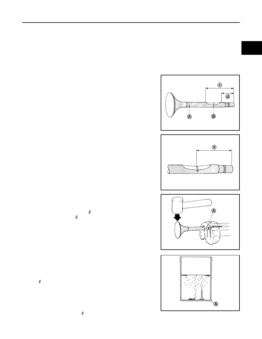
1. Clamp valve stem in a vice.
2. The valve has a specially-hardened surface. To cut through it,

first remove a half-round section, approximately 30 mm (1.18 in)

long using air-powered grinder until black color is removed and

silver color appears.

3. Use hacksaw to cut through approximately half the diameter of

valve stem. Make the serration at a point 40 mm (1.57 in) from

the end of valve stem.

4. Cover the serrated end of the valve with a large shop towel (A).

Strike the valve face end with a hammer, separating it into two

pieces.

5. Fill a bucket, such as a 20   (5-1/4 US gal, 4-3/8 Imp gal) oil

can, with at least 10   (2-5/8 US gal, 2-1/4 lmp gal) of water.

Carefully place the already cut (serrated) valves into the water

one-at-a-time using a set of large tweezers and quickly move

away at least 2.7 m (9 ft).

6. The valves should be placed in a standing position as shown in

the illustration to allow complete reaction. After the bubbling

action has subsided, additional valves can be placed into the

bucket allowing each subsequent chemical reaction to subside.

However, no more than 8 valves should be placed in the same
10   (2-5/8 US gal, 2-1/4 lmp gal) amount of water. The com-

plete chemical reaction may take as long as 4 to 5 hours.

Remove the valves using a set of large tweezers after the chem-

ical reaction has stopped. Afterwards, valves can be disposed

as ordinary scrap.

(A)

: Black color

(B)

: Silver color

(c)

: 47 mm (1.85 in)

(d)

: 17 mm (0.67 in)

JPBIA4964ZZ

(a)

: 40 mm (1.57 in)

JPBIA4965ZZ

JPBIA4966ZZ

A

: Bucket [Such as 20   (5-1/4 US gal, 4-3/8 Imp gal) oil can]

JPBIA4967ZZ

EM-6

< PRECAUTION >

PRECAUTIONS

Precaution for Liquid Gasket

INFOID:0000000011340781

REMOVAL OF LIQUID GASKET SEALING

• After removing the bolts and nuts, separate the mating surface and

remove the liquid gasket using Tool (A).     

CAUTION:

Be careful not to damage the mating surfaces.

• In areas where the cutter is difficult to use, use a plastic hammer to

lightly tap (1) the cutter where the liquid gasket is applied. Use a

plastic hammer to slide (2) the cutter by tapping on the side.

CAUTION:

Do not damage the mating surfaces.

LIQUID GASKET APPLICATION PROCEDURE

1. Using suitable tool (A), remove old liquid gasket adhering to the

liquid gasket application surface and the mating surface.

• Remove liquid gasket completely from the groove of the liquid

gasket application surface, mounting bolts, and bolt holes.

2. Thoroughly clean the mating surfaces and remove adhering

moisture, grease and foreign materials.

3. Attach liquid gasket tube to the suitable tool.

Use Genuine Silicone RTV Sealant, or equivalent. Refer to

GI-22, "Recommended Chemical Products and Sealants"

4. Apply liquid gasket without gaps to the specified location accord-

ing to the specified dimensions.

• If there is a groove for liquid gasket application, apply liquid

gasket to the groove.

• As for bolt holes (B), normally apply liquid gasket inside the

holes. Occasionally, it should be applied outside the holes.

Check to read the text of this manual.

• Within five minutes of liquid gasket application, install the mat-

ing component.

• If liquid gasket protrudes, wipe it off immediately.

• Do not retighten mounting bolts or nuts after the installation.

• After 30 minutes or more have passed from the installation, fill

engine oil and engine coolant. Refer to 

LU-8, "Refilling"

 and 

CO-9, "Refilling"

.

CAUTION:

If there are more specific instructions in the procedures contained in this manual concerning liq-

uid gasket application, observe them.

Tool Number 

: KV10111100 (J-37228)

AWBIA1249GB

JPBIA0053ZZ

EMA0622D

(A)

: Groove

: Inside

JPBIA0010ZZ

NOISE, VIBRATION, AND HARSHNESS (NVH) TROUBLESHOOTING

EM-7

< SYMPTOM DIAGNOSIS >

C

D

E

F

G

H

I

J

K

L

M

A

EM

N

P

O

SYMPTOM DIAGNOSIS

NOISE, VIBRATION, AND HARSHNESS (NVH) TROUBLESHOOTING

NVH Troubleshooting - Engine Noise

INFOID:0000000011279930

ALBIA0916GB

EM-8

< SYMPTOM DIAGNOSIS >

NOISE, VIBRATION, AND HARSHNESS (NVH) TROUBLESHOOTING

Use the Chart Below to Help You Find the Cause of the Symptom

INFOID:0000000011279931

1. Locate the area where noise occurs.
2. Confirm the type of noise.
3. Specify the operating condition of engine.
4. Check specified noise source.
If necessary, repair or replace these parts.

1.

Valve mechanism

2.

Intake and exhaust valve

3.

Water pump

4.

Timing chain

5.

Drive belt

6.

Rotation mechanism

A.

Tappet noise

B.

Camshaft bearing noise

C.

Water pump noise

D.

VTC noise

E.

Timing chain and chain tensioner 
noise

F.

Drive belt noise (slipping)

G.

Main bearing noise

H.

Connecting rod bearing noise

J.

Piston pin noise

K.

Piston slap noise

Location 

of noise

Type of 

noise

Operating condition of engine

Source of 

noise

Check item

Refer-

ence page

Before 

warm-

up

After 

warm-

up

When 

start-

ing

When 

idling

When 

racing

While 

driving

Top of en-
gine
Rocker 
cover
Cylinder 
head

Ticking or 
clicking

C

A

A

B

Tappet 
noise

Valve clearance

EM-121

Rattle

C

A

A

B

C

Camshaft 
bearing 
noise

Camshaft journal clear-
ance
Camshaft runout

EM-121
EM-121

Crank-
shaft pul-
ley
Cylinder 
block 
(Side of 
engine)
Oil pan

Slap or 
knock

A

B

B

Piston pin 
noise

Piston and piston pin 
clearance
Connecting rod bushing 
clearance

EM-130
EM-130

Slap or 
rap

A

B

B

A

Piston 
slap noise

Piston-to-bore clear-
ance
Piston ring side clear-
ance
Piston ring end gap
Connecting rod bend 
and torsion

EM-130
EM-130
EM-130
EM-130

Knock

A

B

C

B

B

B

Connect-
ing rod 
bearing 
noise

Connecting rod bushing 
clearance (Small end)
Connecting rod bearing 
clearance (Big end)

EM-130
EM-130

Knock

A

B

A

B

C

Main bear-
ing noise

Main bearing oil clear-
ance
Crankshaft runout

EM-128
EM-125

Front of 
engine
Timing 
chain cov-
er

Tapping or 
ticking

A

A

B

B

B

Timing 
chain and 
chain ten-
sioner 
noise

Timing chain cracks 
and wear
Timing chain tensioner 
operation

EM-50


Content   ..  558  559  560  561   ..