Nissan Rogue. Manual - part 445


  Index      Nissan     Nissan Rogue (2015 year) - Service and Repair Manual


Search            


Content   ..  443  444  445  446   ..


Nissan Rogue. Manual - part 445


EC-48

< SYSTEM DESCRIPTION >

[QR25DE]

SYSTEM

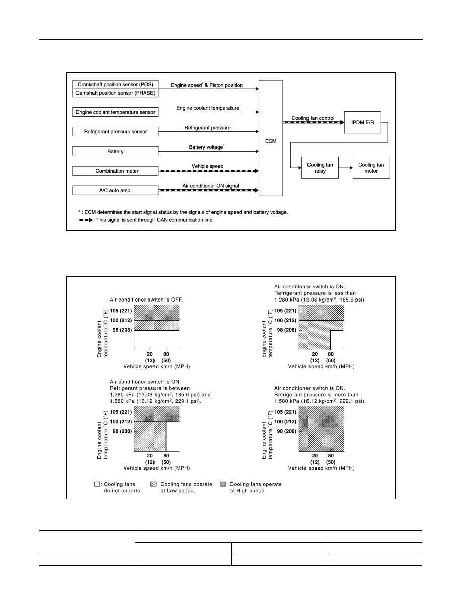
COOLING FAN CONTROL : System Description

INFOID:0000000011277863

SYSTEM DIAGRAM

SYSTEM DESCRIPTION

ECM controls cooling fan speed corresponding to vehicle speed, engine coolant temperature, refrigerant pres-

sure, air conditioner ON signal. Then control system has 3-step control [HIGH/LOW/OFF].

Cooling Fan Operation

Cooling Fan Relay Operation

The ECM controls cooling fan relays through CAN communication line.

JPBIA3233GB

JSBIA4541GB

Cooling fan speed

Cooling fan relay

1

2

3

Stop (OFF)

OFF

OFF

OFF

SYSTEM

EC-49

< SYSTEM DESCRIPTION >

[QR25DE]

C

D

E

F

G

H

I

J

K

L

M

A

EC

N

P

O

AUTOMATIC SPEED CONTROL DEVICE (ASCD)
AUTOMATIC SPEED CONTROL DEVICE (ASCD) : System Description

INFOID:0000000011277864

SYSTEM DIAGRAM

BASIC ASCD SYSTEM

Refer to Owner's Manual for ASCD operating instructions.

Automatic Speed Control Device (ASCD) allows a driver to keep vehicle at predetermined constant speed

without depressing accelerator pedal. Driver can set vehicle speed in advance between approximately 40 km/

h (25 MPH) and 144 km/h (89 MPH).

ECM controls throttle angle of electric throttle control actuator to regulate engine speed.

The ASCD operation status is indicated by two indicators (CRUISE and SET on the information display) on the

combination meter. If any malfunction occurs in ASCD system, SET indicator blinks and ASCD control is deac-

tivated.

NOTE:

Always drive vehicle in safe manner according to traffic conditions and obey all traffic laws.

SET OPERATION

Press MAIN switch. (CRUISE is indicated on the information display.)

When vehicle speed reaches a desired speed between approximately 40 km/h (25 MPH) and 144 km/h (89

MPH), press SET/COAST switch. (Then SET is indicated on the information display.)

ACCELERATE OPERATION

If the RESUME/ACCELERATE switch is pressed during cruise control driving, increase the vehicle speed until

the switch is released or vehicle speed reaches maximum speed controlled by the system.

And then ASCD will keep the new set speed.

CANCEL OPERATION

When any of following conditions exist, cruise operation will be canceled.

• CANCEL switch is pressed

• More than 2 switches at ASCD steering switch are pressed at the same time (Set speed will be cleared)

• Brake pedal is depressed

• Selector lever is changed to N, P, R position

• Vehicle speed decreased to 13 km/h (8 MPH) lower than the set speed

• TCS system is operated

When the ECM detects any of the following conditions, the ECM will cancel the cruise operation and inform

the driver by blinking indicators.

Low (LOW)

OFF

ON

OFF

High (HI)

ON

OFF

ON

Cooling fan speed

Cooling fan relay

1

2

3

JPBIA3210GB

EC-50

< SYSTEM DESCRIPTION >

[QR25DE]

SYSTEM

• Engine coolant temperature is slightly higher than the normal operating temperature, CRUISE indicator may

blink slowly.

When the engine coolant temperature decreases to the normal operating temperature, CRUISE indicator will

stop blinking and the cruise operation will be able to work by pressing SET/COAST switch or RESUME/

ACCELERATE switch.

• Malfunction for some self-diagnoses regarding ASCD control: SET indicator will blink quickly.

If MAIN switch is turned to OFF during ASCD is activated, all of ASCD operations will be canceled and vehicle

speed memory will be erased.

COAST OPERATION

When the SET/COAST switch is pressed during cruise control driving, decrease vehicle set speed until the

switch is released. And then ASCD will keep the new set speed.

RESUME OPERATION

When the RESUME/ACCELERATE switch is pressed after cancel operation other than pressing MAIN switch

is performed, vehicle speed will return to last set speed. To resume vehicle set speed, vehicle condition must

meet following conditions.

• Brake pedal is released

• Selector lever is in other than P and N positions

• Vehicle speed is greater than 40 km/h (25 MPH) and less than 144 km/h (89 MPH)

FUEL FILLER CAP WARNING SYSTEM
FUEL FILLER CAP WARNING SYSTEM : System Description

INFOID:0000000011277865

SYSTEM DIAGRAM

SYSTEM DESCRIPTION

The fuel filler cap warning system alerts the driver to the prevention of the fuel filler being left uncapped and

malfunction occurrences after refueling, by turning ON the fuel filler cap warning display on the combination

meter.

ECM judges a refueled state, based on a fuel level signal transmitted from the combination meter.

When a very small leak is detected through the EVAP leak diagnosis performed after judging the refueled

state, ECM transmits a fuel filler cap warning display signal (request for display ON) to the combination meter

via CAN communication. 

When receiving the signal, the combination meter turns ON the fuel filler cap warning display.

CAUTION:

Check fuel filler cap installation condition when the fuel filler cap warning display turns ON.

Reset Operation

The fuel filler cap warning lamp tunes OFF, according to any condition listed below:

• Reset operation is performed by operating the meter control switch on the combination meter. Refer to 

MWI-

18, "Switch Name and Function"

.

- When the reset operation is performed, the combination meter transmits a fuel filler cap warning reset signal

to ECM via CAN communication. ECM transmits a fuel filler cap warning display signal (request for display

JSBIA0797GB

SYSTEM

EC-51

< SYSTEM DESCRIPTION >

[QR25DE]

C

D

E

F

G

H

I

J

K

L

M

A

EC

N

P

O

OFF) to the combination meter via CAN communication. When receiving the signal, the combination meter

turns OFF the fuel filler cap warning display.

• EVAP leak diagnosis result is normal.

• Fuel refilled.

• DTC erased by using CONSULT.

NOTE:

MIL turns ON if a malfunction is detected in leak diagnosis results again at the trip after the fuel filler cap warn-

ing display turns ON/OFF.

WARNING/INDICATOR/CHIME LIST
WARNING/INDICATOR/CHIME LIST : Warning lamps/Indicator lamps

INFOID:0000000011277866

WARNING/INDICATOR/CHIME LIST : Warning/Indicator (On Information Display)

INFOID:0000000011277867

WARNING

INDICATOR/INFORMATION

WARNING/INDICATOR/CHIME LIST : Malfunction Indicator Lamp (MIL)

INFOID:0000000011277868

DESIGN/PURPOSE

When a malfunction which increases exhaust gases is detected, ECM turns ON MIL and informs the driver of

the necessity of inspection and repair.

Name

Arrangement/Function

Malfunction indicator lamp (MIL)

Regarding the function. Refer to 

EC-51, "WARNING/INDICATOR/CHIME LIST : Mal-

function Indicator Lamp (MIL)"

.

Name

Arrangement/Function

Engine oil pressure warning

Regarding the function. Refer to 

EC-53, "WARNING/INDICATOR/CHIME LIST : En-

gine Oil Pressure Warning"

.

Fuel filler cap warning

Regarding the function. Refer to 

EC-54, "WARNING/INDICATOR/CHIME LIST : Fuel 

Filler Cap Warning"

.

Name

Design

Function

CRUISE indicator
SET indicator

EC-49, "AUTOMATIC SPEED CONTROL DEVICE 
(ASCD) : System Description"

JSBIA3459ZZ


Content   ..  443  444  445  446   ..