Nissan Rogue. Manual - part 444


  Index      Nissan     Nissan Rogue (2015 year) - Service and Repair Manual


Search            


Content   ..  442  443  444  445   ..


Nissan Rogue. Manual - part 444


EC-44

< SYSTEM DESCRIPTION >

[QR25DE]

SYSTEM

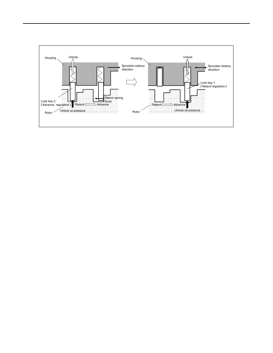
this reason, lock key 2 is released first by being pushed up by unlocking oil pressure. When lock key 2 is

released, some clearance is formed between lock key 1 and the rotor due to sprocket rotational force and

return spring force. Accordingly, lock key 1 is pushed up by unlocking oil pressure and the intermediated

phase lock is released.

When stopping the engine

When the ignition switch is turned from idle state to OFF, ECM receives an ignition switch signal from BCM via

CAN communication and activates the intake valve timing intermediate lock control solenoid valve and drains

oil pressure acting on the lock key before activating the intake valve timing control solenoid valve and operat-

ing the cam phase toward the advance position.

The cam phase is fixed by the lock key when shifting to the intermediated phase and ECM performs Lock

judgment to stop the engine.

When starting the engine

When starting the engine by cold start, ECM judges the locked/unlocked state when ignition switch is turned

ON. When judged as locked state (fixed at the intermediate phase), the intake valve timing intermediate lock

control solenoid valve is activated. Since oil pressure does not act on the lock key even when the engine is

started, the cam phase is fixed at the intermediate phase and the intake valve timing control is not performed.

When the engine stops without locking the cam phase at the intermediate phase due to an engine stall and the

state is not judged as locked, the intake valve timing intermediate lock control solenoid valve and the intake

valve timing control solenoid valve are activated and the cam phase shifts to the advanced position to be

locked at the intermediate phase. Even when not locked in the intermediate lock phase due to no oil pressure

or low oil pressure, a ratchet structure of the camshaft sprocket (INT) rotor allows the conversion to the inter-

mediate phase in stages by engine vibration.

When engine coolant temperature is more than 60

°C, the intake valve timing is controlled by deactivating the

intake valve timing intermediate lock control solenoid valve and releasing the intermediate phase lock.

When the engine is started after warming up, ECM releases the intermediate phase lock immediately after the

engine start and controls the intake valve timing.

EXHAUST VALVE TIMING CONTROL

JPBIA5970GB

SYSTEM

EC-45

< SYSTEM DESCRIPTION >

[QR25DE]

C

D

E

F

G

H

I

J

K

L

M

A

EC

N

P

O

EXHAUST VALVE TIMING CONTROL : System Description

INFOID:0000000011277858

SYSTEM DIAGRAM

SYSTEM DESCRIPTION

This mechanism hydraulically controls cam phases continuously with the fixed operating angle of the exhaust

valve.

The ECM receives signals such as crankshaft position, camshaft position, engine speed, and engine oil tem-

perature. Then, the ECM sends ON/OFF pulse duty signals to the exhaust valve timing (EVT) control solenoid

valve depending on driving status. This makes it possible to control the shut/open timing of the exhaust valve

to increase engine torque and output in a range of high engine speed.

INTAKE MANIFOLD RUNNER CONTROL

JPBIA4761GB

JPBIA5972GB

EC-46

< SYSTEM DESCRIPTION >

[QR25DE]

SYSTEM

INTAKE MANIFOLD RUNNER CONTROL : System Description

INFOID:0000000011277859

SYSTEM DIAGRAM

SYSTEM DESCRIPTION

Intake manifold runner control valve has a valve portion in the intake passage of each cylinder.

While idling and during low engine coolant temperature, the intake manifold runner control valve closes. Thus

the velocity of the air in the intake passage increases, promoting the vaporization of the fuel and producing a

intake manifold runner in the combustion chamber.

Because of this operation, this system tends to increase the burning speed of the gas mixture, improve

exhaust emission, and increase the stability in running conditions.

Also, except when idling and during low engine coolant temperature, this system opens the intake manifold

runner control valve.

In this condition, this system tends to increase power by improving intake efficiency via reduction of intake flow

resistance.

The intake manifold runner control valve is operated by the ECM.

ENGINE PROTECTION CONTROL AT LOW ENGINE OIL PRESSURE
ENGINE PROTECTION CONTROL AT LOW ENGINE OIL PRESSURE : System De-
scription

INFOID:0000000011277860

SYSTEM DIAGRAM

SYSTEM DESCRIPTION

• The engine protection control at low engine oil pressure warns the driver of a decrease in engine oil pres-

sure by the engine oil pressure warning lamp a before the engine becomes damaged.

• When detecting a decrease in engine oil pressure at an engine speed less than 1,000 rpm, ECM transmits

an engine oil pressure warning lamp signal to the combination meter.The combination meter turns ON the

engine oil pressure warning lamp, according to the signal.

*: When detecting a normal engine oil pressure, ECM turns OFF the engine oil pressure warning lamp.

AIR CONDITIONING CUT CONTROL

JPBIA6226GB

JSBIA4201GB

Decrease in engine oil pressure

Engine speed

Combination meter

Fuel cut

Engine oil pressure warning 

lamp

Detection

Less than 1,000 rpm

ON*

NO

1,000 rpm or more

ON

YES

SYSTEM

EC-47

< SYSTEM DESCRIPTION >

[QR25DE]

C

D

E

F

G

H

I

J

K

L

M

A

EC

N

P

O

AIR CONDITIONING CUT CONTROL : System Description

INFOID:0000000011277861

SYSTEM DIAGRAM

SYSTEM DESCRIPTION

This system improves engine operation when the air conditioner is used.

Under the following conditions, the air conditioner is turned off.

• When cranking the engine.

• At high engine speeds.

• When the engine coolant temperature becomes excessively high.

• When operating power steering during low engine speed or low vehicle speed.

• When engine speed is excessively low.

• When refrigerant pressure is excessively low or high.

POWER GENERATION VOLTAGE VARIABLE CONTROL SYSTEM
POWER GENERATION VOLTAGE VARIABLE CONTROL SYSTEM : System De-
scription

INFOID:0000000011277862

DESCRIPTION

ECM transmits a target power generation voltage signal received from IPDM E/R to the generator via LIN

communication.

The generator includes a self-diagnosis function and transmits a diagnosis signal to ECM via LIN communica-

tion when detecting a malfunction. When ECM receives a diagnosis signal, ECM detects DTC and transmits a

charge warning lamp request signal to the combination meter to turn ON the charge warning lamp.

COOLING FAN CONTROL

JSBIA4542GB


Content   ..  442  443  444  445   ..