Nissan Rogue. Manual - part 438


  Index      Nissan     Nissan Rogue (2015 year) - Service and Repair Manual


Search            


Content   ..  436  437  438  439   ..


Nissan Rogue. Manual - part 438


EC-20

< SYSTEM DESCRIPTION >

[QR25DE]

COMPONENT PARTS

Fuel Injector

INFOID:0000000011277824

The fuel injector is a small, precise solenoid valve. When the ECM

supplies a ground to the fuel injector circuit, the coil in the fuel injec-

tor is energized. The energized coil pulls the ball valve back and

allows fuel to flow through the fuel injector into the intake manifold.

The amount of fuel injected depends upon the injection pulse dura-

tion. Pulse duration is the length of time the fuel injector remains

open. The ECM controls the injection pulse duration based on

engine fuel needs.

Fuel Level Sensor Unit and Fuel Pump

INFOID:0000000011277825

FUEL PUMP

The ECM activates the fuel pump for 1 second after the ignition

switch is turned ON to improve engine start ability. If the ECM

receives a engine speed signal from the camshaft position sensor

(PHASE), it knows that the engine is rotating, and causes the pump

to operate. If the engine speed signal is not received when the igni-

tion switch is ON, the engine stalls. The ECM stops pump operation

and prevents battery discharging, thereby improving safety. The

ECM does not directly drive the fuel pump. It sends the control signal

to the fuel pump control module, which in turn controls the fuel

pump.

FUEL LEVEL SENSOR

The fuel level sensor is mounted in the fuel level sensor unit.

The sensor detects a fuel level in the fuel tank and transmits a signal to the combination meter. The combina-

tion meter sends the fuel level sensor signal to the ECM via the CAN communication line.

It consists of two parts, one is mechanical float and the other is variable resistor. Fuel level sensor output volt-

age changes depending on the movement of the fuel mechanical float.

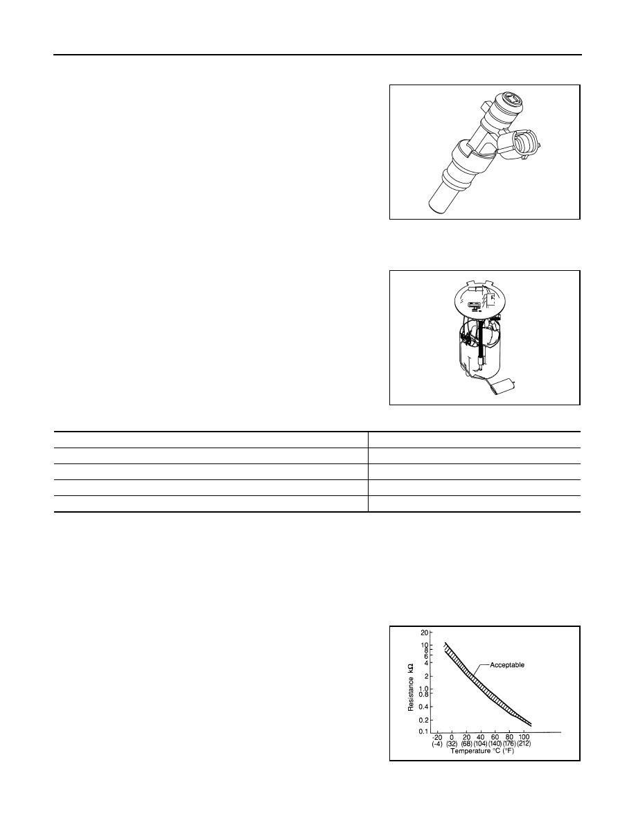
Fuel Tank Temperature Sensor

INFOID:0000000011277826

The fuel tank temperature sensor is used to detect the fuel tempera-

ture inside the fuel tank. The sensor modifies a voltage signal from

the ECM. The modified signal returns to the ECM as the fuel temper-

ature input. The sensor uses a thermistor which is sensitive to the

change in temperature. The electrical resistance of the thermistor

decreases as temperature increases.

<Reference data>

JPBIA5845ZZ

JSBIA4496ZZ

Condition

Fuel pump operation

Ignition switch is turned to ON.

Operates for 1 second.

Engine running and cranking

Operates.

When engine is stopped

Stops in 1.5 seconds.

Except as shown above

Stops.

SEF012P

COMPONENT PARTS

EC-21

< SYSTEM DESCRIPTION >

[QR25DE]

C

D

E

F

G

H

I

J

K

L

M

A

EC

N

P

O

*: These data are reference values and are measured between ECM terminals.

Mass Air Flow Sensor (With Intake Air Temperature Sensor)

INFOID:0000000011277827

MASS AIR FLOW SENSOR

The mass air flow sensor  is placed in the stream of intake air. It

measures the intake flow rate by measuring a part of the entire

intake flow. The MAF sensor controls the temperature of the heater

in sensing element to a certain amount. The temperature distribution

around the heater changes according to the increase in intake air

volume. The change is detected by a thermistor and the air volume

data is sent to ECM by the MAF sensor.

INTAKE AIR TEMPERATURE SENSOR

The intake air temperature sensor is built-into mass air flow sensor. The sensor detects intake air temperature

and transmits a signal to the ECM.

The temperature sensing unit uses a thermistor which is sensitive to the change in temperature.

<Reference data>

*: These data are reference values on the diagnosis tool.

Engine Coolant Temperature Sensor

INFOID:0000000011277828

The engine coolant temperature sensor is used to detect the engine

coolant temperature. The sensor modifies a voltage signal from the

ECM. The modified signal returns to the ECM as the engine coolant

temperature input. The sensor uses a thermistor which is sensitive to

the change in temperature. The electrical resistance of the ther-

mistor decreases as temperature increases.

Fluid temperature

[

°C (°F)]

Voltage* (V)

Resistance (k

Ω)

20 (68)

3.5

2.3 - 2.7

50 (122)

2.2

0.79 - 0.90

PBIA9559J

Intake air temperature

[

°C (°F)]

Voltage

*

 (V)

25 (77)

1.9 – 2.1

80 (176)

3.2 – 3.4

JPBIA5280ZZ

EC-22

< SYSTEM DESCRIPTION >

[QR25DE]

COMPONENT PARTS

<Reference data>

*: These data are reference values and are measured between ECM terminals.

Crankshaft Position Sensor (POS)

INFOID:0000000011277829

The crankshaft position sensor (POS) is located on the oil pan facing

the gear teeth (cogs) of the signal plate. It detects the fluctuation of

the engine revolution.

The sensor consists of a permanent magnet and Hall IC.

When the engine is running, the high and low parts of the teeth

cause the gap with the sensor to change.

The changing gap causes the magnetic field near the sensor to

change.

Due to the changing magnetic field, the voltage from the sensor

changes.

The ECM receives the voltage signal and detects the fluctuation of

the engine revolution.

ECM receives the signals as shown in the figure.

Camshaft Position Sensor (PHASE)

INFOID:0000000011277830

The camshaft position sensor (PHASE) senses the retraction of

intake camshaft to identify a particular cylinder. The camshaft posi-

tion sensor (PHASE) senses the piston position.

When the crankshaft position sensor (POS) system becomes inoper-

ative, the camshaft position sensor (PHASE) provides various con-

trols of engine parts instead, utilizing timing of cylinder identification

signals.

The sensor consists of a permanent magnet and Hall IC.

When engine is running, the high and low parts of the teeth cause

the gap with the sensor to change.

The changing gap causes the magnetic field near the sensor to

change.

Due to the changing magnetic field, the voltage from the sensor changes. 

Engine coolant temperature

[

°C (°F)]

Voltage

*

 (V)

Resistance (k

Ω)

–10 (14)

4.4

7.0 - 11.4

20 (68)

3.5

2.37 - 2.63

50 (122)

2.2

0.68 - 1.00

90 (194)

1.0

0.236 - 0.260

SEF012P

JPBIA5848ZZ

JMBIA0714GB

JPBIA5846ZZ

COMPONENT PARTS

EC-23

< SYSTEM DESCRIPTION >

[QR25DE]

C

D

E

F

G

H

I

J

K

L

M

A

EC

N

P

O

ECM receives the signals as shown in the figure.

Intake Valve Timing Control Solenoid Valve

INFOID:0000000011277831

Intake valve timing control solenoid valve is activated by ON/OFF

pulse duty (ratio) signals from the ECM.

The intake valve timing control solenoid valve changes the oil

amount and direction of flow through intake valve timing control unit

or stops oil flow.

The longer pulse width advances valve angle.

The shorter pulse width retards valve angle.

When ON and OFF pulse widths become equal, the solenoid valve

stops oil pressure flow to fix the intake valve angle at the control

position.

Intake Valve Timing Intermediate Lock Control Solenoid Valve

INFOID:0000000011277832

Intake valve timing intermediate lock control solenoid valve is acti-

vated by ON/OFF signals from the ECM.

The intake valve timing intermediate lock control solenoid valve

opens/closes the path of oil pressure acting on the lock key in the

camshaft sprocket (INT).

• When the solenoid valve becomes ON, oil pressure to the lock key

is trained to perform intermediate lock.

• When the solenoid valve becomes OFF, oil pressure is acted on

the lock key to release the intermediate lock.

Exhaust Valve Timing Control Position Sensor

INFOID:0000000011277833

Exhaust valve timing control position sensor detects the protrusion of

the signal plate installed to the exhaust camshaft front end. 

This sensor signal is used for sensing a position of the exhaust cam-

shaft.

The sensor consists of a permanent magnet and Hall IC.

When engine is running, the high and low parts of the teeth cause

the gap with the sensor to change.

The changing gap causes the magnetic field near the sensor to

change.

Due to the changing magnetic field, the voltage from the sensor

changes. 

JMBIA0714GB

PBIB1842E

PBIB1842E

JPBIA5847ZZ


Content   ..  436  437  438  439   ..