Nissan Rogue. Manual - part 421


  Index      Nissan     Nissan Rogue (2015 year) - Service and Repair Manual


Search            


Content   ..  419  420  421  422   ..


Nissan Rogue. Manual - part 421


DLN-128

< UNIT DISASSEMBLY AND ASSEMBLY >

[REAR FINAL DRIVE: R145]

DIFFERENTIAL ASSEMBLY

1. Install side gear thrust washers with the same thickness as the

ones installed prior to disassembly or reinstall the old ones on

the side gears.

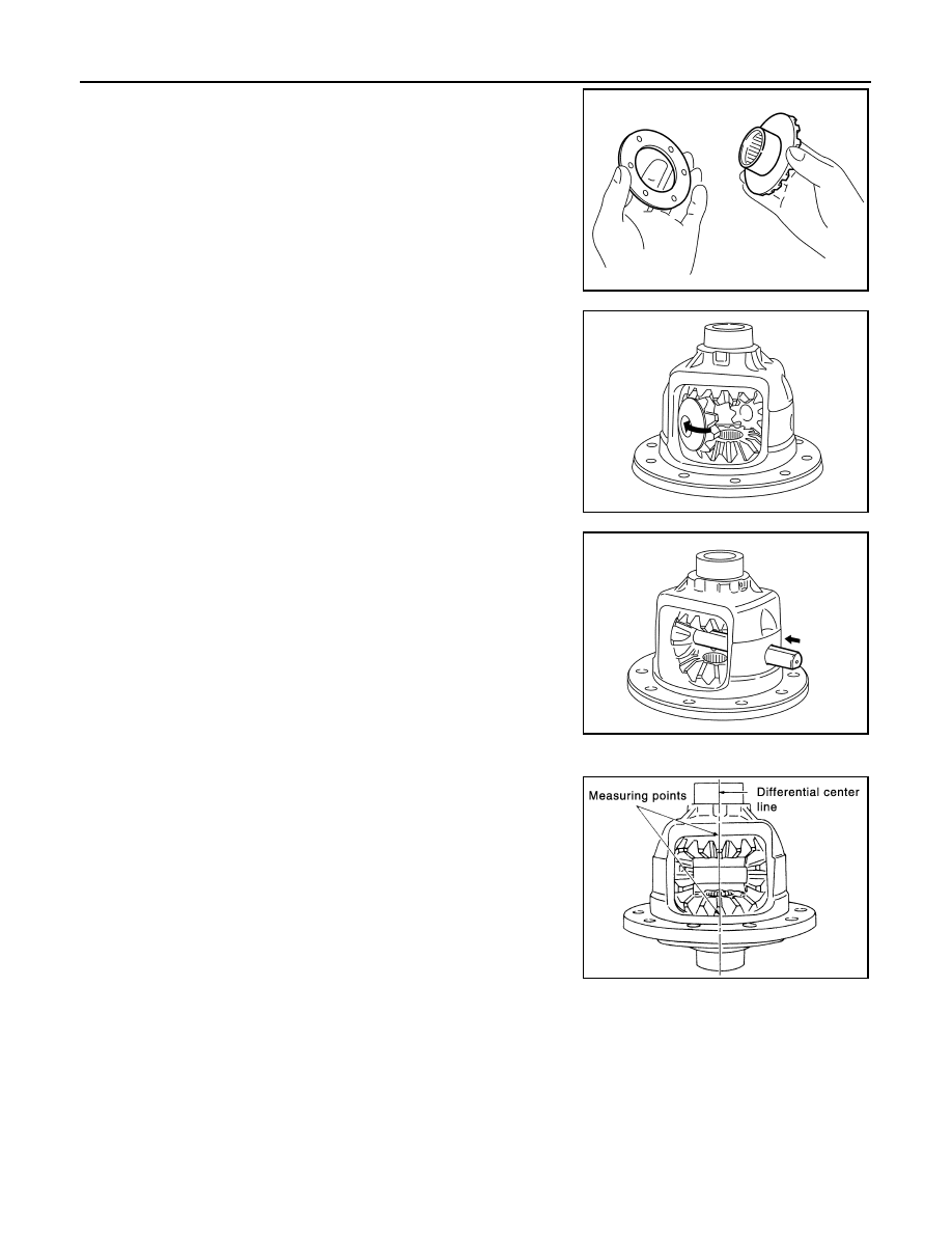
2. Install side gears and side gear thrust washers into differential

case.

3. Align 2 pinion mate gears in diagonally opposite positions, then

rotate and install them into differential case after installing thrust

washer to pinion mate gear.

4. Align the lock pin holes on differential case with pinion mate

shaft, and install pinion mate shaft.

5. Measure side gear end play. If necessary, select the appropriate side gear thrust washers.
a. Place differential assembly straight up so that side gear to be

measured comes upward.

SDIA0193J

SDIA0194J

SDIA0195J

JPDID0205GB

DIFFERENTIAL ASSEMBLY

DLN-129

< UNIT DISASSEMBLY AND ASSEMBLY >

[REAR FINAL DRIVE: R145]

C

E

F

G

H

I

J

K

L

M

A

B

DLN

N

O

P

b. Using feeler gauge, measure the clearance between side gear

back and differential case at 3 different points, while rotating

side gear. Average the 3 readings, and then measure the clear-

ance of the other side as well.

CAUTION:

To prevent side gear from tilting, insert feeler gauges with

the same thickness from both sides.

• If the back clearance is outside the specification, use a thicker/

thinner side gear thrust washer to adjust. For selecting thrust

washer, refer to the latest parts information.

CAUTION:

Select a side gear thrust washer for right and left individu-

ally.

6. Drive a lock pin into pinion mate shaft, using the pin punch

(commercial service tool).

CAUTION:

Never reuse lock pin.

7. Press side bearing inner races to differential assembly, using the

drifts (A and B).

CAUTION:

• Never reuse side bearing inner race.

• Apply gear oil to side bearing.

8. Apply thread locking sealant into the thread hole of drive gear.

CAUTION:

Clean and degrees drive gear back and threaded holes suf-

ficiently.

9. Install the drive gear to differential assembly.

CAUTION:

Align the matching mark of differential assembly and drive

gear.

Side gear back clear-
ance

: Refer to 

DLN-142, "Differ-

ential Side Gear Clear-
ance"

.

When the back clearance 
is large

: Use a thicker thrust washer.

When the back clearance 
is small

: Use a thinner thrust washer.

PDIA0576E

PDIA0759J

A

: Drift [SST: KV40105020 ( — )]

B

: Drift [SST: KV40105020 ( — )]

JSDIA5288ZZ

SPD554

DLN-130

< UNIT DISASSEMBLY AND ASSEMBLY >

[REAR FINAL DRIVE: R145]

DIFFERENTIAL ASSEMBLY

10. Tighten the bolts in a crisscross fashion to the specified torque.

• For tightening torque, refer to 

DLN-125, "Exploded View"

.

CAUTION:

Apply anti-corrosion oil to the thread and seat of mounting

bolts.

11. Assemble side bearing outer races to inner races.

CAUTION:

• Never reuse side bearing outer race.

• Apply gear oil to side bearing.

12. Install new side bearing adjusting shims (2 pieces for one side)

with the same thickness as the ones installed prior to disassem-

bly or re-install the old ones, on side bearing outer race of differ-

ential assembly.

If side bearing adjusting shims have been already selected, use them.

13. Set the drifts (A and B) to the right and left side bearing adjusting

shims individually. Compress differential assembly and side

bearing to gear carrier assembly to install differential assembly.

CAUTION:

• The drift shall be placed on the center of the adjusting

shims.

• The pressure shall be as low as possible to install differ-

ential assembly into gear carrier assembly. The maximum

pressure shall be 10 kN (1 ton, 1.1 US ton, 1.0 Imp ton).

• If the adjusting shims are installed by tapping, the gear carrier may be damaged. Avoid tapping.

14. Install dummy cover set [SST: KV381086S1 ( — )], check and adjust drive gear runout, tooth contact,

backlash, and total preload torque. Refer to 

DLN-131, "Adjustment"

.

15. Remove dummy cover set.
16. Install stud bolt to rear cover.

CAUTION:

Screw the stud bolt until the thread becomes invisible by applying a torque of 20 N·m (2.0 kg-m, 15

ft-lb) or less.

17. Apply liquid gasket to mating surface of rear cover.

CAUTION:

• Remove old gasket adhering to the mounting surfaces.

Also remove any moisture, oil, or foreign material adher-

ing to the mounting surfaces.

• The width of sealant bead is approximately 3 mm (0.12 in).

Apply sealant evenly.

18. Set the drifts (A and B) to the right and left side bearing adjusting

shims individually. Compress differential assembly and side

bearing to install rear cover.

CAUTION:

• The drift shall be placed on the center of the adjusting

shims.

A

: Drift [KV40100610 (J-26089)]

B

: Drift [KV40100610 (J-26089)]

PDIA0466E

JSDIA5289ZZ

JSDIA5290ZZ

A

: Drift [KV40100610 (J-26089)]

B

: Drift [KV40100610 (J-26089)]

JSDIA5286ZZ

DIFFERENTIAL ASSEMBLY

DLN-131

< UNIT DISASSEMBLY AND ASSEMBLY >

[REAR FINAL DRIVE: R145]

C

E

F

G

H

I

J

K

L

M

A

B

DLN

N

O

P

• The pressure shall be as low as possible to install differential assembly into gear carrier assem-

bly. The maximum pressure shall be 10 kN (1 ton, 1.1 US ton, 1.0 Imp ton).

• If the adjusting shims are installed by tapping, the gear carrier may be damaged. Avoid tapping.

19. Tighten rear cover mounting bolts to the specified torque.

• For tightening torque, refer to 

DLN-125, "Exploded View"

.

20. Using the drift (A) [SST: KV38100200 (J-26233)], drive side oil

seals until it becomes flush with the gear carrier end.

CAUTION:

• Never reuse oil seals.

• When installing, do not incline oil seals.

• Apply multi-purpose grease onto oil seal lips, and gear oil

onto the circumference of oil seal.

21. Check total preload torque. Refer to 

DLN-131, "Adjustment"

.

Adjustment

INFOID:0000000011278422

TOTAL PRELOAD TORQUE

1. Remove electric controlled coupling assembly. Refer to 

DLN-122, "Disassembly and Assembly"

.

2. Rotate drive pinion back and forth 2 to 3 times to check for unusual noise and rotation malfunction.
3. Rotate drive pinion at least 20 times to check for smooth opera-

tion of the bearing.

4. Fit drive pinion socket onto drive pinion spline. Measure the total

preload, using the preload gauge and drive pinion socket.

NOTE:

Total preload torque = Pinion bearing torque + Side bearing torque

• If measured value is out of the specification, disassemble it to check and adjust each part. Adjust the pinion

bearing preload and side bearing preload.

Adjust the pinion bearing preload first, then adjust the side bearing preload.

DRIVE GEAR RUNOUT

1. Remove rear cover. Refer to 

DLN-126, "Disassembly and Assembly"

.

2. Following the procedure below, install a dummy cover set [SST: KV381086S1 (

)] to gear car-

rier.

JSDIA5291ZZ

A

: Preload gauge [SST: ST3127S000 (J-25765-A)]

B

: Drive pinion socket [SST: KV38109500 (

)]

Standard
Total preload torque

: Refer to 

DLN-142, "Pre-

load Torque"

.

When the preload torque is large

On pinion bearings:

Replace the collapsible spacer.

On side bearings:

Use thinner side bearing adjusting shims. For selecting adjusting 
shim, refer to the latest parts information.

When the preload is small

On pinion bearings:

Tighten the drive pinion nut.

On side bearings:

Use thicker side bearing adjusting shims. For selecting adjusting 
shim, refer to the latest parts information.

PDIA0048E


Content   ..  419  420  421  422   ..