Nissan Rogue. Manual - part 422


  Index      Nissan     Nissan Rogue (2015 year) - Service and Repair Manual


Search            


Content   ..  420  421  422  423   ..


Nissan Rogue. Manual - part 422


DLN-132

< UNIT DISASSEMBLY AND ASSEMBLY >

[REAR FINAL DRIVE: R145]

DIFFERENTIAL ASSEMBLY

a. Set dummy cover shims [SST: KV38108630 (

)] to the right and left side bearing adjusting

shims.

b. Temporarily tighten dummy cover [SST: KV38108610 (

)] to gear carrier.

c.

Position dummy cover spacers [SST: KV38108621 (

)] to dummy cover [SST: KV38108610

(

)].

d. Tighten rear cover mounting bolts to the specified torque. Refer to 

DLN-125, "Exploded View"

.

e. Tighten dummy cover spacer mounting bolts evenly to the specified torque.

3. Fit a dial indicator to the drive gear back face.
4. Rotate the drive gear to measure runout.

• If the runout is outside of the repair limit, check drive gear

assembly condition; foreign material may be caught between

drive gear and differential case, or differential case or drive

gear may be deformed, etc.

CAUTION:

Replace drive gear and drive pinion as a set.

TOOTH CONTACT

1. Remove rear cover. Refer to 

DLN-126, "Disassembly and Assembly"

.

2. Following the procedure below, install a dummy cover set [SST: KV381086S1 (

)] to gear car-

rier.

a. Set dummy cover shims [SST: KV38108630 (

)] to the right and left side bearing adjusting

shims.

b. Temporarily tighten dummy cover [SST: KV38108610 (

)] to gear carrier.

c.

Position dummy cover spacers [SST: KV38108621 (

)] to dummy cover [SST: KV38108610

(

)].

d. Tighten rear cover mounting bolts to the specified torque. Refer to 

DLN-125, "Exploded View"

.

e. Tighten dummy cover spacer mounting bolts evenly to the specified torque.

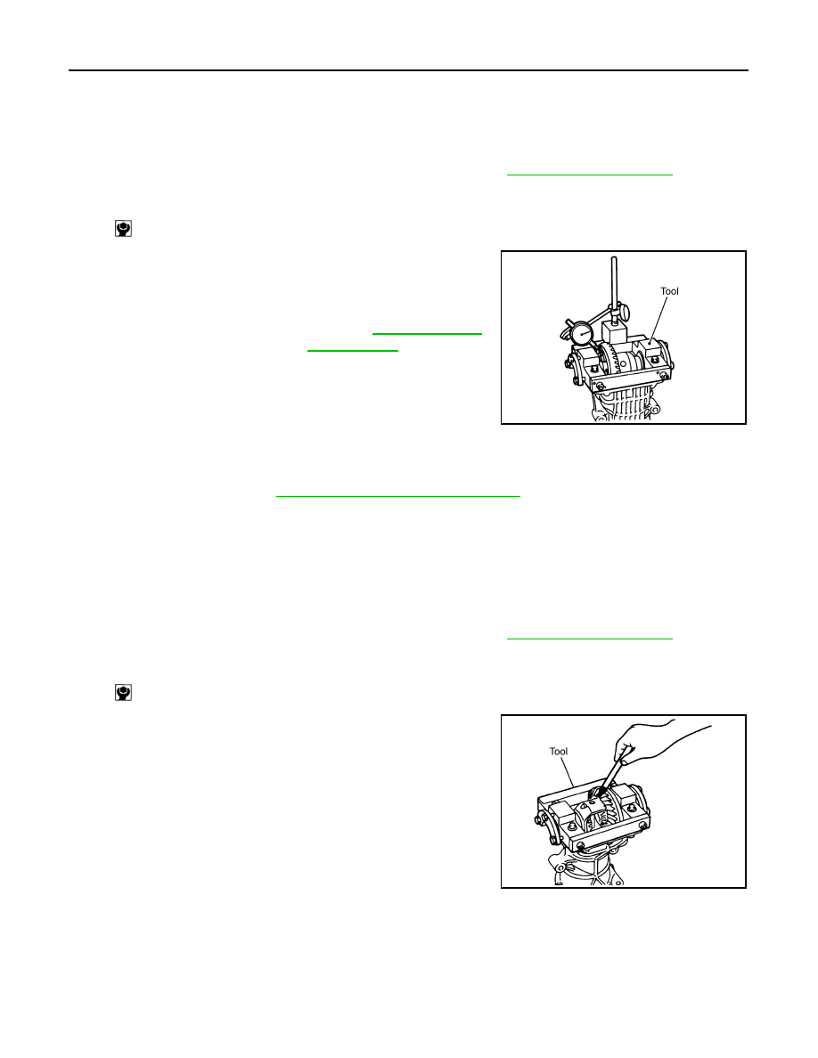
3. Apply red lead to drive gear.

CAUTION:

Apply red lead to both the faces of 3 to 4 gears at 4 loca-

tions evenly spaced on drive gear.

: 5.9 N·m (0.6 kg-m, 52 in-lb)

Limit
Drive gear back face 
runout

: Refer to 

DLN-142, "Drive 

Gear Runout"

.

PDIA0050E

: 5.9 N·m (0.6 kg-m, 52 in-lb)

PDIA0051E

DIFFERENTIAL ASSEMBLY

DLN-133

< UNIT DISASSEMBLY AND ASSEMBLY >

[REAR FINAL DRIVE: R145]

C

E

F

G

H

I

J

K

L

M

A

B

DLN

N

O

P

4. Rotate drive gear back and forth several times, check drive pin-

ion gear to drive gear tooth contact.

CAUTION:

Check tooth contact on drive side and reverse side.

Tooth Contact Judgment Guide

5. If tooth contact is improperly adjusted, follow the procedure

below to adjust the pinion height (dimension X).

SDIA0570E

SDIA2549E

SDIA0517E

DLN-134

< UNIT DISASSEMBLY AND ASSEMBLY >

[REAR FINAL DRIVE: R145]

DIFFERENTIAL ASSEMBLY

• If the tooth contact is near the face (face contact), or near the

heel (heel contact), thicken drive pinion gear adjusting shim to

move drive pinion closer to drive gear.

For selecting adjusting shim, refer to the latest parts informa-

tion.

• If the tooth contact is near the flank (flank contact), or near the

toe (toe contact), thin drive pinion gear adjusting shim to move

drive pinion farther from drive gear.

For selecting adjusting shim, refer to the latest parts informa-

tion.

BACKLASH

1. Remove rear cover. Refer to 

DLN-126, "Disassembly and Assembly"

.

2. Following the procedure below, install a dummy cover set [SST: KV381086S1 (

)] to gear car-

rier.

a. Set dummy cover shims [SST: KV38108630 (

)] to the right and left side bearing adjusting

shims.

b. Temporarily tighten dummy cover [SST: KV38108610 (

)] to gear carrier.

c.

Position dummy cover spacers [SST: KV38108621 (

)] to dummy cover [SST: KV38108610

(

)].

d. Tighten rear cover mounting bolts to the specified torque. Refer to 

DLN-125, "Exploded View"

.

e. Tighten dummy cover spacer mounting bolts evenly to the specified torque.

3. Fit a dial indicator to the drive gear face to measure the back-

lash.

• If the backlash is outside of the specified value, change the

thickness of side bearing adjusting shims.

PDIA0440E

PDIA0441E

: 5.9 N·m (0.6 kg-m, 52 in-lb)

Standard
Backlash

: Refer to 

DLN-142, "Backlash"

.

When the backlash is large:

Make drive gear back adjusting shims thicker, and drive 
gear front adjusting shims thinner. For selecting ad-
justing shim, refer to the latest parts information.

When the backlash is small:

Make drive gear back adjusting shims thinner, and 
drive gear front adjusting shims thicker. For selecting 
adjusting shim, refer to the latest parts information.

PDIA0049E

DIFFERENTIAL ASSEMBLY

DLN-135

< UNIT DISASSEMBLY AND ASSEMBLY >

[REAR FINAL DRIVE: R145]

C

E

F

G

H

I

J

K

L

M

A

B

DLN

N

O

P

Inspection

INFOID:0000000011278423

INSPECTION AFTER DISASSEMBLY

Drive Gear and Drive Pinion

• Clean up the disassembled parts.

• If the gear teeth never mesh or line-up correctly, determine the cause and adjust or replace as necessary.

• If the gears are worn, cracked, damaged, pitted or chipped (by friction) noticeably, replace with new drive

gear and drive pinion as a set.

Bearing

• Clean up the disassembled parts.

• If any chipped (by friction), pitted, worn, rusted or scratched marks, or unusual noise from the bearing is

observed, replace as a bearing assembly (as a new set).

Oil Seal

• Whenever disassembled, replace.

• If wear, deterioration of adherence (sealing force lips), or damage is detected on the lips, replace them.

Differential Assembly

DIFFERENTIAL CASE

• Clean up the disassembled parts.

• If any wear or crack on the contact sides of the differential case is found, replace.

SIDE GEAR AND PINION MATE GEAR

• Clean up the disassembled parts.

• If any cracks or damage on the surface of the tooth is found, replace.

• If any worn or chipped mark on the contact sides of the thrust washer is found, replace.

SIDE GEAR THRUST WASHER AND PINION MATE THRUST WASHER

• Clean up the disassembled parts.

• If it is chipped (by friction), damaged, or unusually worn, replace.


Content   ..  420  421  422  423   ..