Nissan Rogue. Manual - part 419
DLN-120
< UNIT REMOVAL AND INSTALLATION >
[REAR FINAL DRIVE: R145]
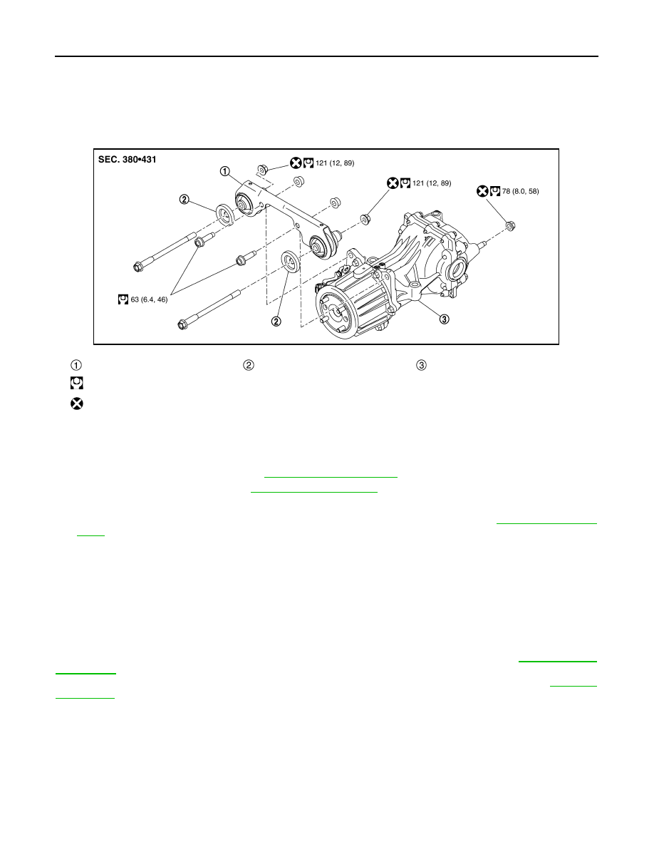
REAR FINAL DRIVE ASSEMBLY
UNIT REMOVAL AND INSTALLATION
REAR FINAL DRIVE ASSEMBLY
Exploded View
INFOID:0000000011278416
Removal and Installation
INFOID:0000000011278417
REMOVAL
1. Remove rear propeller shaft. Refer to
2. Remove rear drive shafts. Refer to
.
3. Disconnect AWD solenoid harness connector.
4. Remove rear final drive breather hose and electric controlled coupling breather hose.
.
5. Support final drive assembly with a suitable jack.
6. Remove final drive nuts and final drive bolts with power tool.
If necessary, remove final drive bracket and washer with power tool.
CAUTION:
Secure final drive assembly to a suitable jack while removing it.
INSTALLATION
Installation is in the reverse order of removal.
CAUTION:
When replacing rear final drive assembly, perform writing unit characteristics. Refer to
.
When oil leaks while removing final drive assembly, check oil level after the installation. Refer to
Final drive mounting bracket
Mounting stopper
Rear final drive assembly
: N·m (kg-m, ft-lb)
: Always replace after every disassembly.
JSDIA5398GB