Nissan Rogue. Manual - part 412


  Index      Nissan     Nissan Rogue (2015 year) - Service and Repair Manual


Search            


Content   ..  410  411  412  413   ..


Nissan Rogue. Manual - part 412


DLN-92

< UNIT DISASSEMBLY AND ASSEMBLY >

[TRANSFER: TY21C]

TRANSFER CASE

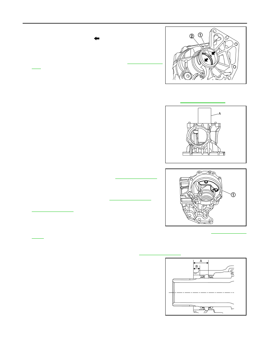
7. Remove the ring gear bearing adjusting shim (transfer case

side) (1) and ring gear bearing outer race (transfer case side) (2)
by tapping from the 2 cutouts (

) on the transfer case.

CAUTION:

Do not damage transfer case.

8. Remove plug and gasket.
9. Perform inspection after disassembly. Refer to 

DLN-93, "Inspec-

tion"

.

Assembly

INFOID:0000000011278380

1. Select the ring gear bearing adjusting shim (transfer case side). Refer to 

DLN-85, "Adjustment"

.

2. Install the selected ring gear bearing adjusting shim (transfer

case side) and ring gear bearing outer race (transfer case side)

using suitable tool (A).

CAUTION:

• Do not reuse ring gear bearing.

• Apply gear oil to the ring gear bearing.

3. Install baffle plate (1).
4. Install ring gear shaft assembly. Refer to 

DLN-79, "Assembly"

.

CAUTION:

Protect transfer case oil seals beforehand from being dam-

aged by the spline of ring gear shaft.

5. Install drive pinion assembly. Refer to 

DLN-84, "Assembly"

.

6. Install transfer cover to check and adjust each part. Refer to

DLN-75, "Assembly"

.

NOTE:

At this timing, O-ring installing to transfer cover is not necessary.

Install O-ring after backlash and tooth contact are checked.

7. Check backlash, tooth contact, total preload and companion flange runout. Refer to 

DLN-85, "Adjust-

ment"

.

CAUTION:

Measure the total preload without oil seals of transfer cover and transfer case.

8. Reinstall transfer cover for installing O-ring. Refer to 

DLN-75, "Assembly"

.

9. Install oil seals using suitable tool.

CAUTION:

• When checking the total preload torque, measure it with-

out the oil seal, then install the oil seal.

• Do not reuse the oil seal.

• When installing, do not incline oil seal.

• Apply multi-purpose grease onto oil seal lips, and gear oil

onto the circumference of the oil seal.

• Do not damage oil seals by spline of ring gear shaft.

10. After installing oil seals to transfer case, remove wrapped vinyl from the spline of ring gear shaft.
11. Apply multi-purpose grease lightly and evenly onto an O-ring, and install it to the transfer case.

JSDIA3984ZZ

JSDIA3998ZZ

(A)

: 24.8 mm (0.976 in)

(B)

: 10.3 mm (0.406 in)

JSDIA3982ZZ

JSDIA4047ZZ

TRANSFER CASE

DLN-93

< UNIT DISASSEMBLY AND ASSEMBLY >

[TRANSFER: TY21C]

C

E

F

G

H

I

J

K

L

M

A

B

DLN

N

O

P

CAUTION:

• Do not reuse O-ring.

• When installing O-ring, do not use a suitable tool.

• Do not damage O-ring.

Inspection

INFOID:0000000011278381

INSPECTION AFTER DISASSEMBLY

Check items below. If necessary, replace them with new ones.

Case

Check the bearing mounting surface for wear, cracks and damages.

DLN-94

< SERVICE DATA AND SPECIFICATIONS (SDS) 

[TRANSFER: TY21C]

SERVICE DATA AND SPECIFICATIONS (SDS)

SERVICE DATA AND SPECIFICATIONS (SDS)

SERVICE DATA AND SPECIFICATIONS (SDS)

General Specifications

INFOID:0000000011278382

 (US pt, Imp pt)

Preload Torque

INFOID:0000000011278383

Unit: N·m (kg-m, in-lb)

Backlash

INFOID:0000000011278384

Unit: mm (in)

Companion Flange Runout

INFOID:0000000011278385

Unit: mm (in)

Applied model

AWD

QR25DE

CVT

Transfer model

TY21C

Oil Type

MA-11, "Fluids and Lubricants"

Oil capacity (Approx.)

 0.31 (5/8 pt, 1/2 pt)

Gear ratio

0.404

Number of teeth

Ring gear

42

Drive pinion

17

Item

Standard

Pinion bearing preload

0.25 – 1.15 (0.03 – 0.11, 3.0 – 10.0)

Total preload

With all oil seals

P

1

 + 0.7 – 1.0 (0.08 – 0.1, 7.0 – 8.0)

Without oil seals (for transfer cover and 
transfer case)

P

1

 + 0.5 – 0.8 (0.06 – 0.08, 5.0 – 7.0)

Item

Standard

Ring gear to drive pinion

0.16 – 0.21 (0.0063 – 0.0083)

Item

Limit

Companion flange face (inner side of the propeller shaft mounting 
bolt holes)

0.15 (0.0059)

Inside of companion flange (socket diameter)

0.1 (0.004)

PRECAUTIONS

DLN-95

< PRECAUTION >

[REAR PROPELLER SHAFT: C-CVJ-C]

C

E

F

G

H

I

J

K

L

M

A

B

DLN

N

O

P

PRECAUTION

PRECAUTIONS

Precaution for Supplemental Restraint System (SRS) "AIR BAG" and "SEAT BELT 
PRE-TENSIONER"

INFOID:0000000011278386

The Supplemental Restraint System such as “AIR BAG” and “SEAT BELT PRE-TENSIONER”, used along

with a front seat belt, helps to reduce the risk or severity of injury to the driver and front passenger for certain

types of collision. Information necessary to service the system safely is included in the SR and SB section of

this Service Manual.

WARNING:

• To avoid rendering the SRS inoperative, which could increase the risk of personal injury or death in

the event of a collision which would result in air bag inflation, all maintenance must be performed by

an authorized NISSAN/INFINITI dealer.

• Improper maintenance, including incorrect removal and installation of the SRS, can lead to personal

injury caused by unintentional activation of the system. For removal of Spiral Cable and Air Bag

Module, see the SR section.

• Do not use electrical test equipment on any circuit related to the SRS unless instructed to in this

Service Manual. SRS wiring harnesses can be identified by yellow and/or orange harnesses or har-

ness connectors.

PRECAUTIONS WHEN USING POWER TOOLS (AIR OR ELECTRIC) AND HAMMERS

WARNING:

• When working near the Airbag Diagnosis Sensor Unit or other Airbag System sensors with the Igni-

tion ON or engine running, DO NOT use air or electric power tools or strike near the sensor(s) with a

hammer. Heavy vibration could activate the sensor(s) and deploy the air bag(s), possibly causing

serious injury.

• When using air or electric power tools or hammers, always switch the Ignition OFF, disconnect the

battery and wait at least three minutes before performing any service.

Precaution for Propeller Shaft

INFOID:0000000011278387

• Replace the propeller shaft assembly if there is a breakage or deflection on tube.

• Never hit the tube or apply an impact on it during repair service. Never damage the tube as well.

• The joint cannot be disassembled. Never disassemble it.

• If constant velocity joint was bent during propeller shaft assembly removal, installation, or transportation, its

boot may be damaged. Wrap boot interference area to metal part with shop cloth or rubber to protect boot

from breakage.


Content   ..  410  411  412  413   ..