Nissan Rogue. Manual - part 393
DLN-16
< SYSTEM DESCRIPTION >
[TRANSFER: TY21C]
SYSTEM
NOTE:
• If the AWD warning displays during driving but remains not displayed after the engine is restarted, the sys-
tem is normal. If it again displays after driving for some time, vehicle must be inspected.
• When there is a difference of revolution speed between the front and rear wheel the shift occasionally
changes to direct 4-wheel driving conditions automatically. This is not a malfunction.
INFORMATION DISPLAY (COMBINATION METER)
INFORMATION DISPLAY (COMBINATION METER) : AWD Warning
INFOID:0000000011278301
DESIGN/PURPOSE
AWD warning is displayed when the AWD system has a malfunction. AWD warning indicates that the vehicle
is in fail-safe mode or protection function mode.
SYNCHRONIZATION WITH MASTER WARNING LAMP
Applicable
For master warning lamp, refer to
DLN-17, "WARNING/INDICATOR/CHIME LIST : Warning/Indicator (On
.
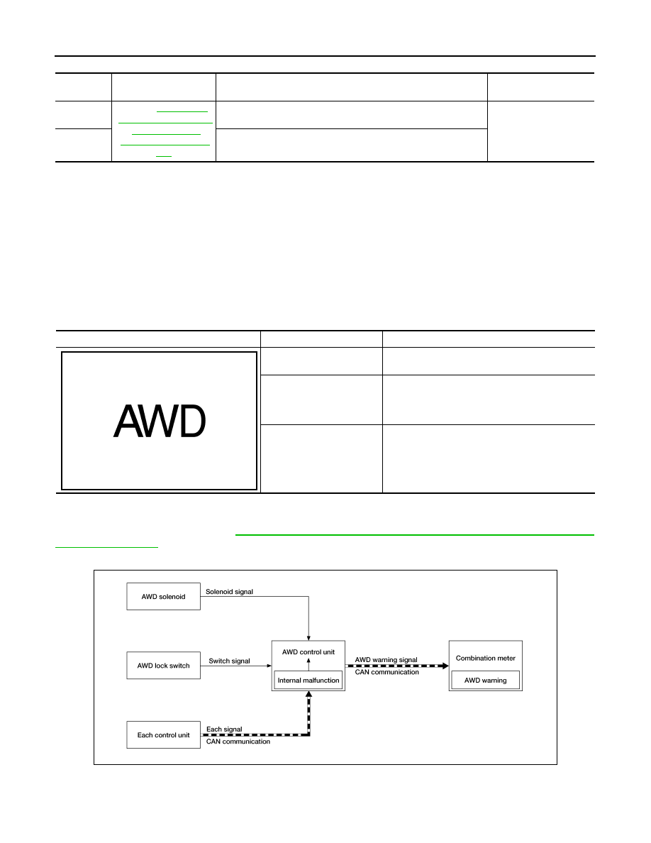
SYSTEM DIAGRAM
SIGNAL PATH
• The AWD control unit judges and decides a mode from among normal mode, fail-safe mode, and protection
function mode, according to signals received from each switch, sensor, and control unit.
DTC
AWD warning (on infor-
mation display)
Error area and root cause
Contents of protection
function
—
Refer to
Rear final drive assembly in protection mode. It is not malfunction.
(Internal temperature rise of electronic controlled coupling)
Shuts down AWD sys-
tem temporarily
(Front wheel drive)
—
Malfunction in each tire or different tire diameter
Symbol
Message
Condition
AWD Error
See Owner’s Manual
AWD system malfunction.
AWD High Temp.
Stop vehicle
Protection function is activated due to heavy load to
electric controlled coupling. (AWD system is not
malfunctioning and AWD system changes to rear
wheel drive.)
Tire Size Incorrect
See Owner’s Manual
Large difference in diameter of front/rear tires.
JSDIA4707ZZ
ALDIA0514GB