Nissan Rogue. Manual - part 235


  Index      Nissan     Nissan Rogue (2015 year) - Service and Repair Manual


Search            


Content   ..  233  234  235  236   ..


Nissan Rogue. Manual - part 235


DAS

U111A REAR CAMERA IMAGE SIGNAL CIRCUIT

DAS-111

< DTC/CIRCUIT DIAGNOSIS >

[DRIVER ASSISTANCE SYSTEM]

C

D

E

F

G

H

I

J

K

L

M

B

N

P

A

Is the inspection result normal?

YES

>> Replace around view monitor control unit. Refer to 

AV-380, "Removal and Installation"

.

NO

>> Replace rear view camera. Refer to 

AV-383, "Removal and Installation"

.

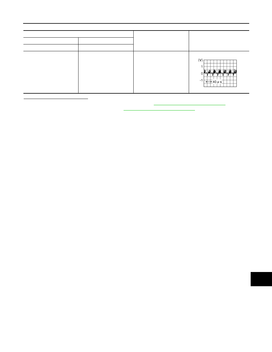
Around view monitor control unit connector M114

Condition

Reference value

(+)

(

−)

Terminal

Terminal

53

54

CAMERA switch is ON or se-
lector lever in R (reverse).

JSNIA0834GB

DAS-112

< DTC/CIRCUIT DIAGNOSIS >

[DRIVER ASSISTANCE SYSTEM]

U111B SIDE CAMERA RH IMAGE SIGNAL CIRCUIT

U111B SIDE CAMERA RH IMAGE SIGNAL CIRCUIT

DTC Logic

INFOID:0000000011419757

DTC DETECTION LOGIC

Diagnosis Procedure

INFOID:0000000011459688

Regarding Wiring Diagram information, refer to 

AV-253, "Wiring Diagram"

.

WITHOUT DRIVER ASSISTANCE SYSTEM

1.

CHECK RH SIDE CAMERA POWER SUPPLY AND GROUND CIRCUIT CONTINUITY

1. Turn ignition switch OFF.

2. Disconnect around view monitor control unit and RH side camera connectors.

3. Check continuity between around view monitor control unit connector M103 and RH side camera connec-

tor D107.

4. Check continuity between around view monitor control unit connector M103 and ground.

Is the inspection result normal?

YES

>> GO TO 2.

NO

>> Repair or replace harness or connectors.

2.

CHECK RH SIDE CAMERA POWER SUPPLY VOLTAGE

1. Connect around view monitor control unit and RH side camera connectors.

2. Turn ignition switch ON.

3. Check voltage between around view monitor control unit connector M103 and ground.

Is the inspection result normal?

YES

>> GO TO 3.

NO

>> Replace around view monitor control unit. Refer to 

AV-380, "Removal and Installation"

.

3.

CHECK RH SIDE CAMERA IMAGE SIGNAL AND IMAGE SIGNAL GROUND CIRCUIT CONTINUITY

1. Turn ignition switch OFF.

CONSULT Display

DTC Detection Condition

Possible Cause

Right side display output signal 
diagnosis (Harness disconnec-
tion)
[U111B]

Right side camera image signal circuit open or 
short.

Check right side camera image signal circuit.

Around view monitor control unit

RH side camera

Continuity

Connector

Terminals

Connector

Terminals

M103

34

D107

7

Yes

33

8

Around view monitor control unit

Ground

Continuity

Connector

Terminal

M103

34

No

Around view monitor control unit

Ground

Condition

Voltage

(Approx.)

Connector

Terminal

M103

34

CAMERA switch is ON or 
selector lever in R (re-
verse).

6.0 V

DAS

U111B SIDE CAMERA RH IMAGE SIGNAL CIRCUIT

DAS-113

< DTC/CIRCUIT DIAGNOSIS >

[DRIVER ASSISTANCE SYSTEM]

C

D

E

F

G

H

I

J

K

L

M

B

N

P

A

2. Disconnect around view monitor control unit and RH side camera connectors.

3. Check continuity between around view monitor control unit connector M103 and RH side camera connec-

tor D107.

4. Check continuity between around view monitor control unit connector M103 and ground.

Is the inspection result normal?

YES

>> GO TO 4.

NO

>> Repair or replace harness or connectors.

4.

CHECK RH SIDE CAMERA IMAGE SIGNAL

1. Connect around view monitor control unit and RH side camera connectors.

2. Turn ignition switch ON.

3. Check signal between the terminals of around view monitor control unit connector M103.

Is the inspection result normal?

YES

>> Replace around view monitor control unit. Refer to 

AV-380, "Removal and Installation"

.

NO

>> Replace RH side camera. Refer to 

AV-382, "Removal and Installation"

.

WITH DRIVER ASSISTANCE SYSTEM

1.

CHECK RH SIDE CAMERA POWER SUPPLY AND GROUND CIRCUIT CONTINUITY

1. Turn ignition switch OFF.

2. Disconnect around view monitor control unit and RH side camera connectors.

3. Check continuity between around view monitor control unit connector M114 and RH side camera connec-

tor D107.

4. Check continuity between around view monitor control unit connector M114 and ground.

Around view monitor control unit

RH side camera

Continuity

Connector

Terminals

Connector

Terminals

M103

36

D107

16

Yes

35

15

Around view monitor control unit

Ground

Continuity

Connector

Terminal

M103

36

No

Around view monitor control unit connector M103

Condition

Reference value

(+)

(

−)

Terminal

Terminal

36

35

CAMERA switch is ON or se-
lector lever in R (reverse).

JSNIA0834GB

Around view monitor control unit

RH side camera

Continuity

Connector

Terminals

Connector

Terminals

M114

62

D107

7

Yes

64

8

DAS-114

< DTC/CIRCUIT DIAGNOSIS >

[DRIVER ASSISTANCE SYSTEM]

U111B SIDE CAMERA RH IMAGE SIGNAL CIRCUIT

Is the inspection result normal?

YES

>> GO TO 2.

NO

>> Repair or replace harness or connectors.

2.

CHECK RH SIDE CAMERA POWER SUPPLY VOLTAGE

1. Connect around view monitor control unit and RH side camera connectors.

2. Turn ignition switch ON.

3. Check voltage between around view monitor control unit connector M114 and ground.

Is the inspection result normal?

YES

>> GO TO 3.

NO

>> Replace around view monitor control unit. Refer to 

AV-380, "Removal and Installation"

.

3.

CHECK RH SIDE CAMERA IMAGE SIGNAL AND IMAGE SIGNAL GROUND CIRCUIT CONTINUITY

1. Turn ignition switch OFF.

2. Disconnect around view monitor control unit and RH side camera connectors.

3. Check continuity between around view monitor control unit connector M114 and RH side camera connec-

tor D107.

4. Check continuity between around view monitor control unit connector M114 and ground.

Is the inspection result normal?

YES

>> GO TO 4.

NO

>> Repair or replace harness or connectors.

4.

CHECK RH SIDE CAMERA IMAGE SIGNAL

1. Connect around view monitor control unit and RH side camera connectors.

2. Turn ignition switch ON.

3. Check signal between the terminals of around view monitor control unit connector M114.

Around view monitor control unit

Ground

Continuity

Connector

Terminal

M114

62

No

Around view monitor control unit

Ground

Condition

Voltage

(Approx.)

Connector

Terminal

M114

62

CAMERA switch is ON or 
selector lever in R (re-
verse).

6.0 V

Around view monitor control unit

RH side camera

Continuity

Connector

Terminals

Connector

Terminals

M114

65

D107

16

Yes

66

15

Around view monitor control unit

Ground

Continuity

Connector

Terminal

M114

65

No


Content   ..  233  234  235  236   ..