Nissan Rogue. Manual - part 231


  Index      Nissan     Nissan Rogue (2015 year) - Service and Repair Manual


Search            


Content   ..  229  230  231  232   ..


Nissan Rogue. Manual - part 231


DAS

REAR VIEW CAMERA CALIBRATION

DAS-95

< BASIC INSPECTION >

[DRIVER ASSISTANCE SYSTEM]

C

D

E

F

G

H

I

J

K

L

M

B

N

P

A

REAR VIEW CAMERA CALIBRATION

Description

INFOID:0000000011277229

Always perform the calibration after removing and installing or replacing the rear view camera:

• AVM control unit

• Rear view camera

CAUTION:

• Place the vehicle on level ground when the calibration is performed.

• Follow the CONSULT when performing the calibration. (Rear view camera calibration cannot be

operated without CONSULT).

Work Procedure (Preparation)

INFOID:0000000011445122

1.

PERFORM SELF-DIAGNOSIS

Perform “Self Diagnostic Result” of “AVM” using CONSULT. 
Is any DTC detected?

Except “U1308”>> Perform diagnosis on the detected DTC and repair or replace the applicable item. Refer to

DAS-48, "DTC Index"

.

“U1308” or no DTC>> GO TO 2.

2.

PREPARATION BEFORE REAR VIEW CAMERA CALIBRATION

NOTE:

Select the “AVM” to diagnose the AVM control unit using CONSULT.

1. Perform pre-inspection for diagnosis. 

2. Adjust the tire pressure to the specified pressure value.

3. Maintain no-load in vehicle.

4. Check if coolant and engine oil are filled up to correct level and fuel tank is full.

5. Situate vehicle where the camera is exposed at an atmosphere temperature between 0

°C (32°F) and

30

°C (86°F).

6. Move the shift selector to P (Park) and release the parking brake.

7. Clean the rear view camera.

>> GO TO 3.

3.

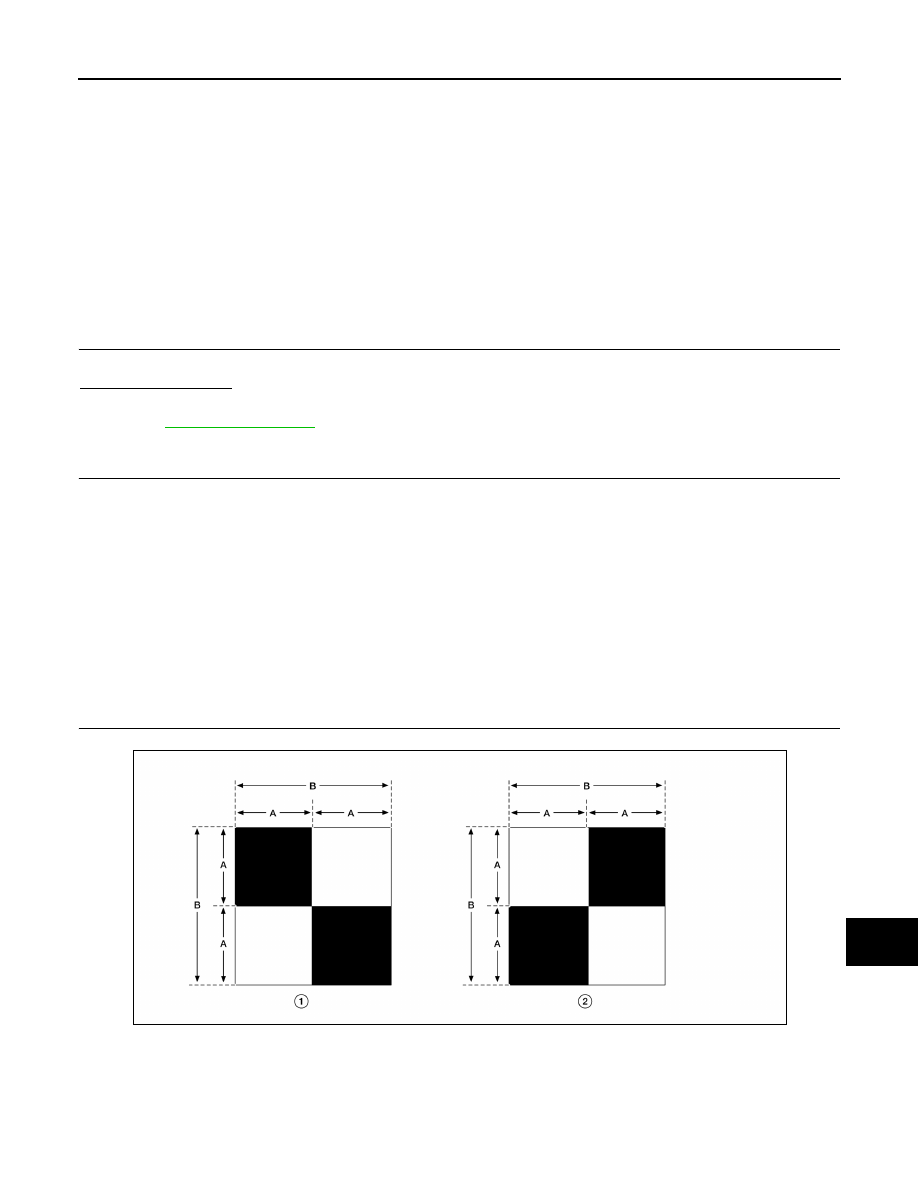
PREPARATION OF CALIBRATION TARGET MARK

Prepare the calibration target mark according to the following figure:

ALOIA0186ZZ

(1) : Left and right targets
(2) : Center target

DAS-96

< BASIC INSPECTION >

[DRIVER ASSISTANCE SYSTEM]

REAR VIEW CAMERA CALIBRATION

>> Refer to 

DAS-96, "Work Procedure (Target Setting)"

.

Work Procedure (Target Setting)

INFOID:0000000011445123

CAUTION:

• Perform this operation in a horizontal position where there is a clear view for 3 m (9.84 ft) backward

and 4 m (13.12 ft) wide.

• Place the target in a well-lighted location. (Poor lighting may make it hard to adjust.)

• The target may not be detected when it shines by the reflected light of the sun or lighting.

• The target may not be detected when there is the same pattern of black and white as the target when

the pattern is within 0.5 m (1.64 ft) from either side and upward/downward position from the target. (It

is desirable that the vehicle is positioned on a single-color floor.)

1.

TARGET SETTING

1. Mark points “A”, “B”, “C” and “D” at the center of the lateral sur-

face of each wheel.

NOTE:

Hang a string with a cone from the fender so as to pass through

the center of wheel, and then mark a point at the center of the

lateral surface of the wheel.

2. Draw line “LH” passing through points “A” and “B” on the left side

of vehicle. 

NOTE:

Approximately 2.2 m (7.22 ft) or more at the rear from the rear

axle.

3. Mark point “E” on the line “LH” at the positions 2125 mm (83.66

in) from point “B”.

4. Draw line “RH” passing through points “C” and “D” on the right side of vehicle in the same way as step 2.

5. Mark point “F” on the line “RH” at the positions 2125 mm (83.66 in) from point “D”.

6. Draw line “RW” passing through the points “E” and “F” on the rear of the vehicle.

NOTE:

Approximately 1.8 m (5.91 ft) or more at both left and right sides from vehicle center.

7. Mark point “C

t

” at the center of point “E” and “F” on the line “RW”.

(A) : Side of the black or white area = 200 mm (7.87 in)
(B) : Side of the square target

= 400 mm (15.75 in)

Side distance (S

d

): “B” – “E” (“D” – “F”)  

2194 mm (86.38 in) 

Left distance (L

d

): “C

t

” – “L

t

”                  :  1500 mm (59.06 in) 

Right distance (R

d

): “C

t

” – “R

t

”               :  1500 mm (59.06 in) 

ALOIA0187GB

PKIB7667E

DAS

REAR VIEW CAMERA CALIBRATION

DAS-97

< BASIC INSPECTION >

[DRIVER ASSISTANCE SYSTEM]

C

D

E

F

G

H

I

J

K

L

M

B

N

P

A

CAUTION:

Make sure that “E” to “C

t

” is equal to “F” to “C

t

”.

8. Mark point “Lt” and “Rt” on the line “RW” at the positions 1500 mm (59.06 in) from point “Ct”.

9. Position the center of the target mark to point of “Ct”.

CAUTION:

Make sure that the black/white pattern of the center target is rotated as compared with the left and

right targets.

>> Go to 

DAS-97, "Work Procedure (Rear View Camera Calibration)"

.

Work Procedure (Rear View Camera Calibration)

INFOID:0000000011445124

CAUTION:

Perform the calibration under the specified vehicle condition (fuel full, no-load, specified tire pressure,

etc.). Refer to 

DAS-95, "Work Procedure (Preparation)"

.

1.

CHECK REAR VIEW CAMERA HEIGHT

Measure the rear view camera height “H”.

>> GO TO 2.

2.

REAR VIEW CAMERA CALIBRATION

1. Select “AVM” using CONSULT.

2. Select “REAR CAMERA ITS” in “Work support”.

3. Select “OK”.

CAUTION:

• Perform the calibration after the ignition or engine has been kept on for at least 10 minutes to

stabilize camera.

• Operate CONSULT outside the vehicle, and close all doors to retain appropriate vehicle attitude. 

4. Input the rear view camera height “H”, and then touch “APPLY”.

5. Confirm that the same value is displayed on the center display.

6. Confirm the following items:

-

The target should be accurately placed.

-

The vehicle should be stopped.

-

The vehicle should be under the specified vehicle condition.

ALOIA0192GB

AWOIA0076ZZ

DAS-98

< BASIC INSPECTION >

[DRIVER ASSISTANCE SYSTEM]

REAR VIEW CAMERA CALIBRATION

7. Select “Start” to perform calibration.

8. Confirm the displayed item.

-

“Completed”: Select “Completion”.

-

Otherwise, perform the following services:

NOTE:

Replace camera unit if “00H Routine not activated” or “10H Writing error” are repeatedly indicated during the

above two services are performed.

9. Confirm that “Completed” is displayed and then select “End” to close the calibration procedure.

>> GO TO 3.

3.

PERFORM SELF-DIAGNOSIS

Perform “Self Diagnostic Result” of “AVM” using CONSULT.
Is any DTC detected?

YES

>> Perform diagnosis on the detected DTC and repair or replace the applicable item. Refer to 

DAS-

48, "DTC Index"

.

NO

>> GO TO 4.

4.

ACTION TEST

Test the system operation by action test. Refer to 

AV-280, "CONFIGURATION (AV CONTROL UNIT) :

Description"

.

>> Work End.

Displayed item

Possible cause

Service procedure

SUSPENSION

Temporary malfunction in internal processing of the rear 
view camera.

Go back to Step 1

00H Routine not ac-
tivated

Rear view camera unit malfunction.

Position the target appro-
priately again. Perform 
the aiming again. Refer 
to 

DAS-96, "Work Proce-

dure (Target Setting)"

.

10H Writing error

• Temporary malfunction in internal processing of the 

rear view camera.

•  Rear view camera malfunction.

X AIMING NG Y
(X: 0 - 7, Y: 1 - 8)

• A target is not-yet-placed.

(The rear view camera cannot detect a target.)

• The position of the rear view camera is not correct.
• Inappropriate work environment.
• Inappropriate vehicle condition.

Position the target appro-
priately again. Perform 
the aiming again. Refer 
to 

DAS-95, "Work Proce-

dure (Preparation)"

.

ABNORMALLY COM-
PLETED


Content   ..  229  230  231  232   ..