Nissan Rogue. Manual - part 220
DAS
REAR VIEW CAMERA WASHER CONTROL UNIT
DAS-51
< ECU DIAGNOSIS INFORMATION >
[DRIVER ASSISTANCE SYSTEM]
C
D
E
F
G
H
I
J
K
L
M
B
N
P
A
Terminal
(Wire color)
Description
Condition
Standard value
Reference val-
ue
(Approx.)
+
–
Signal name
Input/
Output
1
(SB)
Ground
Air pump power supply
Output
Ignition
switch
ON
Air pump operated.
9.5 - 16 V
Battery voltage
Air pump not operated.
0 - 0.1 V
0 V
2
(LG)
Air pump ground
—
Ignition
switch
ON
—
0 - 0.1 V
0 V
3
(GR)
Washer motor power supply
Output
Ignition
switch
ON
Rear view camera washer
motor operated.
0 - 0.1 V
0 V
Rear view camera washer
motor not operated.
9.5 - 16 V
Battery voltage
4
(Y)
Washer motor ground
—
—
0 - 0.1 V
0 V
5
(B)
Ground
—
Ignition
switch
ON
—
0 - 0.1 V
0 V
6
(V)
Communication line ground
—
Ignition
switch
ON
—
0 - 0.1 V
0 V
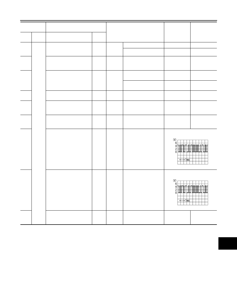
7
(L)
Communication line
(PUMP
→ CAMERA)
Output
Ignition
switch
ON
—
Input the waveform synchronized
with the communication status.
8
(BR)
Communication line
(CAMERA
→ PUMP)
Input
Ignition
switch
ON
—
Input the waveform synchronized
with the communication status.
12
(LG)
Ignition power supply
Input
Ignition
switch
ON
—
9.5 - 16 V
Battery voltage
PKIB5039J
PKIB5039J