Nissan Rogue. Manual - part 192


  Index      Nissan     Nissan Rogue (2015 year) - Service and Repair Manual


Search            


Content   ..  190  191  192  193   ..


Nissan Rogue. Manual - part 192


REPLACEMENT OPERATIONS

BRM-41

< REMOVAL AND INSTALLATION >

C

D

E

F

G

H

I

J

L

M

A

B

BRM

N

O

P

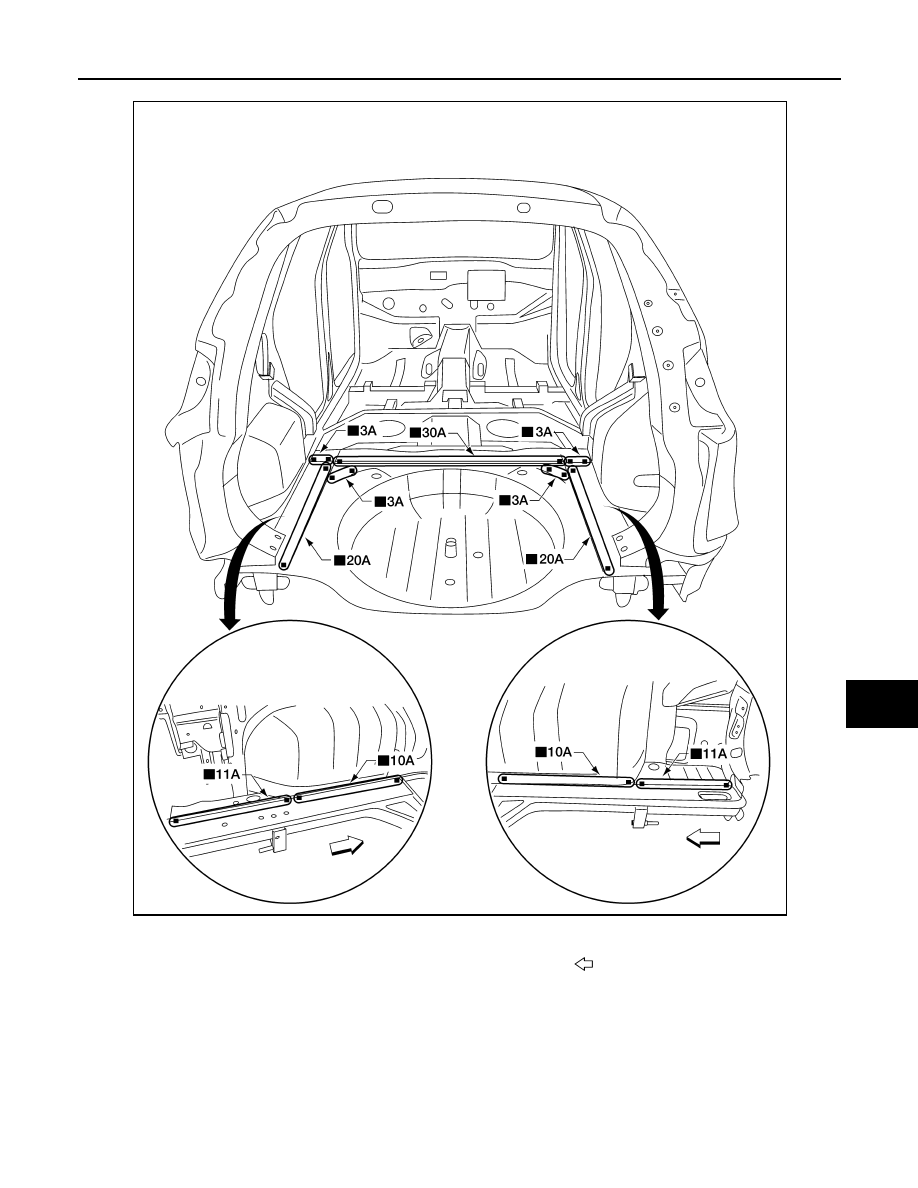
Rear Side Member Extension

INFOID:0000000011280094

Work after rear panel has been removed.

Replacement parts

z

Rear floor rear

z

Rear floor rear side 

Front

AWKIA2865ZZ

BRM-42

< REMOVAL AND INSTALLATION >

REPLACEMENT OPERATIONS

Replacement parts

z

Rear side member extension (LH)

Front

AWKIA2866ZZ

BODY ALIGNMENT

BRM-43

< SERVICE DATA AND SPECIFICATIONS (SDS) 

C

D

E

F

G

H

I

J

L

M

A

B

BRM

N

O

P

SERVICE DATA AND SPECIFICATIONS (SDS)

BODY ALIGNMENT

Body Center Marks

INFOID:0000000011280095

A mark has been placed on each part of the body to indicate the vehicle center. When repairing parts dam-

aged by an accident which might affect the vehicle frame (members, pillars, etc.), more accurate and effective

repair will be possible by using these marks together with body alignment specifications.

Unit: mm (in)

Front

Points

Portion

Marks

A

Cowl top extension

Hole 

φ7 (0.28)

B

Center cowl top

Embossment

C

Front roof

Embossment

D

Rear roof

Embossment

AWKIA2867ZZ

BRM-44

< SERVICE DATA AND SPECIFICATIONS (SDS) 

BODY ALIGNMENT

Description

INFOID:0000000011280096

• All dimensions indicated in the figures are actual.

• When using a tracking gauge, adjust both pointers to equal length. Then check the pointers and gauge itself

to make sure there is no free play.

• When a measuring tape is used, check to be sure there is no elongation, twisting or bending.

• Measurements should be taken at the center of the mounting holes.

• An asterisk (*) following the value at the measuring point indicates that the measuring point on the other side

is symmetrically the same value.

• The coordinates of the measurement points are the distances measured from the standard line of 

″X″, ″Y″

and 

″Z″.

″Z″: Imaginary base line [200 mm (7.87 in) below datum line (″0Z″ at design plan)]

Engine Compartment

INFOID:0000000011280097

MEASUREMENT

E

Trans control reinforcement

Hole 14

×12 (0.55×0.47)

F

Rear seat crossmember

Embossment

Points

Portion

Marks

1.

Vehicle center

2.

Front axle center

3.

Imaginary base line

JSKIA0073GB


Content   ..  190  191  192  193   ..