Content .. 1218 1219 1220 1221 ..
Nissan Rogue. Manual - part 1220
WCS
SYSTEM
WCS-9
< SYSTEM DESCRIPTION >
C
D
E
F
G
H
I
J
K
L
M
B
A
O
P
WARNING CANCEL CONDITIONS
Warning is canceled if any of the following conditions are fulfilled:
SIGNAL PATH
Combination meter sounds integrated buzzer when it judges that parking brake release warning chime is nec-
essary from signals below.
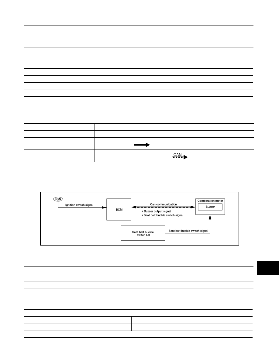
SEAT BELT REMINDER WARNING CHIME
SEAT BELT REMINDER WARNING CHIME : Seat belt Warning
INFOID:0000000011276458
SYSTEM DIAGRAM
WARNING OPERATION CONDITIONS
If all of the following conditions are fulfilled:
WARNING CANCEL CONDITIONS
Warning is canceled if any of the following conditions are fulfilled:
SIGNAL PATH
Parking brake
During the operation (parking brake switch ON).
Vehicle speed
Approximately 4.3 MPH (7 km/h) or more.
Operation conditions
Operation conditions
Ignition switch
OFF
Parking brake
Release condition (parking brake switch OFF).
Vehicle speed
Approximately 1.9 MPH (3 km/h) or less.
Signal name
Signal source
Ignition switch signal
—
Parking brake switch signal
Parking brake switch
Combination meter
Vehicle speed signal
ABS actuator and electric unit (control unit)
Combination meter
AWNIA2652GB
Operation conditions
Ignition switch
ON
Driver seat belt
Unfastened [seat belt buckle switch LH ON]
Operation conditions
Ignition switch
OFF
Driver seat belt
Fastened (seat belt buckle switch LH OFF)
6 seconds after the start of warning sound.