Nissan Rogue. Manual - part 1221


  Index      Nissan     Nissan Rogue (2015 year) - Service and Repair Manual


Search            


Content   ..  1219  1220  1221  1222   ..


Nissan Rogue. Manual - part 1221


WCS

DIAGNOSIS SYSTEM (COMBINATION METER)

WCS-13

< SYSTEM DESCRIPTION >

C

D

E

F

G

H

I

J

K

L

M

B

A

O

P

NOTE:

When the trip reset switch is pressed during the indication of Test order “10,” test item returns to Test order “2.”
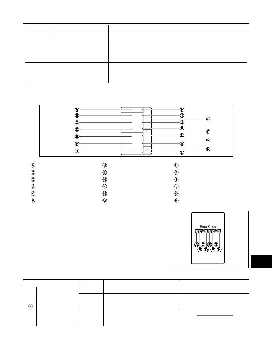
*1: Color Check

*2: Error Code

9

error code

*2

Displays the error code of the following items:
• Speedometer
• Tachometer
• Engine coolant temperature gauge
• Fuel gauge
• Meter control switch

10

Warning/indicator lamp check

All warning/indicator lamp illuminate.
NOTE:
• When either one of them does not turn ON, replace combination meter.
• SRS air bag warning lamp and security indicator lamp are not illuminate.

Blue

Red

Pink

Green

Light blue

Yellow

White

White

Black

Light blue

Black

Pink

Black

Blue

Black

Dark blue

White

Blue

Test order

Test item

Description

JSNIA5944ZZ

JSNIA5945ZZ

Item

Code

Description

Action to take/Reference

Speedometer

0

Normal

1

A vehicle speed signal cannot be received 
from ABS actuator and electric unit (control 
unit).

Perform “Self Diagnostic Result” of 
“ABS.”
Refer to 

BRC-53, "DTC Index"

.

2

A vehicle speed signal received from the 
ABS actuator and electric unit (control unit) 
is abnormal.

WCS-14

< SYSTEM DESCRIPTION >

DIAGNOSIS SYSTEM (COMBINATION METER)

How to Reset Error Code

Error codes stored in combination meter can be reset by following the instructions below:

1. Turn ignition switch OFF.

2. While pressing the trip reset switch, turn ignition switch ON. 

3. Keep the trip reset switch for 1 seconds or more.

4. Press the trip reset switch at least 3 times. (Within 7 seconds after the ignition switch is turned ON.)

5. Turn ignition switch OFF.

6. Perform self-diagnosis and check that the error codes are reset.

CONSULT Function (METER/M&A)

INFOID:0000000011403294

APPLICATION ITEMS

CONSULT can display each diagnostic item using the diagnostic test modes shown.

SELF DIAG RESULT

Refer to 

MWI-31, "DTC Index"

.

DATA MONITOR

Display Item List

Tachometer

0

Normal

1

An engine speed signal cannot be received 
from ECM.

Perform “Self Diagnostic Result” of 
“ECM.” 
Refer to 

EC-96, "DTC Index"

.

Fuel gauge

0

Normal

1

Fuel gauge circuit is short.

Refer to 

MWI-63, "Component Function 

Check"

.

2

Fuel gauge circuit is open.

Engine coolant temper-
ature gauge

0

Normal

1

An engine coolant temperature signal can-
not be received from ECM.

Perform “Self Diagnostic Result” of 
“ECM.” 
Refer to 

MWI-31, "DTC Index"

.

Meter control switch 

0

Normal

1

When judging that the illumination control 
switch signal circuit is shorted for 5 minutes 
or more.

Refer to 

MWI-69, "Diagnosis Proce-

dure"

.

2

When judging that the trip reset switch sig-
nal circuit is shorted for 5 minutes or more.

3

When judging that the both switch signal cir-
cuit is shored for 5 minutes or more.

0

Displays “0” constantly.

0

Displays “0” constantly.

0

Displays “0” constantly.

Item

Code

Description

Action to take/Reference

METER/M&A Diagnosis mode

Description

Self Diagnostic Result

Displays combination meter self-diagnosis results.

Data Monitor

Displays combination meter input/output data in real time.

Warning History

Lighting history of the warning lamp and indicator lamp can be checked.

CAN DIAG SUPPORT MNTR

The result of transmit/receive diagnosis of CAN communication can be read.

WCS

DIAGNOSIS SYSTEM (COMBINATION METER)

WCS-15

< SYSTEM DESCRIPTION >

C

D

E

F

G

H

I

J

K

L

M

B

A

O

P

X: Applicable

Display item [Unit]

MAIN

SIGNALS

Description

SPEED METER

X

Displays the value of vehicle speed signal.

SPEED OUTPUT
[mph or km/h]

X

Vehicle speed signal value transmitted to other units via CAN communication.

ODO OUTPUT
[mph or km/h]

Odometer signal value transmitted to other units via CAN communication.

TACHO METER
[rpm]

X

Value of the engine speed signal received from ECM via CAN communication.

FUEL METER
[L]

X

Fuel level indicated on combination meter.

W TEMP METER
[

°F] or [°C]

X

Displays the value of engine coolant temperature signal, which is input from ECM.

ABS W/L
[On/Off]

Displays [ON/OFF] condition of ABS warning indicator.

VDC/TCS IND 
[On/Off]

Displays [ON/OFF] condition of VDC OFF indicator lamp.

SLIP IND
[On/Off]

Displays [ON/OFF] condition of SLIP indicator lamp.

BRAKE W/L
[On/Off]

Displays [ON/OFF] condition of brake warning indicator.

DOOR W/L
[On/Off]

Displays [ON/OFF] condition of door or liftgate warning message in the informa-
tion display.

HI-BEAM IND
[On/Off]

Displays [ON/OFF] condition of high beam indicator.

TURN IND
[On/Off]

Displays [ON/OFF] condition of turn indicator.

LIGHT IND
[On/Off]

Displays [ON/OFF] condition of light indicator.

FR FOG IND
[On/Off]

Displays [ON/OFF] condition of front fog lamp indicator.

OIL W/L
[On/Off]

Displays [ON/OFF] condition of low oil pressure warning message in the informa-
tion display.

O/D OFF IND
[On/Off]

Displays [ON/OFF] condition of O/D OFF indicator.

DDS W/L
[On/Off]

Displays [ON/OFF] condition of hill descent control warning indicator.

MIL
[On/Off] 

Displays [ON/OFF] condition of malfunction indicator.

SPORT IND
[On/Off]

Displays [ON/OFF] condition of SPORT indicator.

CHAGE W/L
[On/Off]

Displays [ON/OFF] condition of charge warning indicator.

4WD LOCK IND
[On/Off]

Displays [ON/OFF] condition of AWD LOCK indicator lamp.

4WD W/L
[On/Off]

Displays [ON/OFF] condition of AWD warning message in the information display.

FUEL W/L
[On/Off]

Displays [ON/OFF] condition of low-fuel warning message.

WASHER W/L
[On/Off]

Displays [ON/OFF] condition of low washer fluid warning message.

WCS-16

< SYSTEM DESCRIPTION >

DIAGNOSIS SYSTEM (COMBINATION METER)

WORK SUPPORT

WARNING HISTORY

Special menu

AIR PRES W/L
[On/Off]

Displays [ON/OFF] condition of tire pressure warning lamp.

KEY G/Y W/L
[On/Off]

Displays [ON/OFF] condition of key green warning lamp.

EPS W/L
[On/Off]

Displays [ON/OFF] condition of EPS warning indicator.

LCD

Displays the value of Intelligent Key system message indication.

ECO MODE IND
[On/Off]

Displays [ON/OFF] condition of ECO mode indicator lamp.

SHIFT IND
[P, R, N, D, L]

Displays shift selector position.

FUEL CAP W/L
[On/Off]

Displays [ON/OFF] condition of loose fuel cap warning message.

O/D OFF SW
[On/Off]

Displays [ON/OFF] condition of O/D Off switch.

PKB SW
[On/Off]

Displays [ON/OFF] condition of parking brake switch.

BUCKLE SW
[On/Off]

Displays [ON/OFF] condition of seat belt buckle switch LH.

PASS BUCKLE SW
[On/Off]

Displays [ON/OFF] condition of seat belt buckle switch RH.

ECO MODE SW
[On/Off]

Displays [ON/OFF] condition of ECO mode switch.

BRAKE OIL SW
[On/Off]

Displays [ON/OFF] condition of brake fluid level switch.

DISTANCE
[Mi] or [km]

Displays distance to empty.

OUTSIDE TEMP
[

°F or °C]

Displays the ambient air temperature which is input from the ambient sensor.

FUEL LOW SIG
[On/Off]

Displays [ON/OFF] condition of low-fuel warning signal.

STRG SW INPUT
[SW 1-SW 10, NOT INPUT]

Displays [SW 1-SW 10, NOT INPUT] condition of steering switches.

BUZZER
[On/Off]

X

Buzzer status (in the combination meter) is detected from the buzzer output signal 
received from each unit via CAN communication and the warning output condition 
of the combination meter.

BSW IND
[On/Off]

Displays [ON/OFF] condition of blind spot warning indicator.

BSW W/L
[On/Off]

Displays [ON/OFF] condition of blind spot warning message in the information dis-
play.

Display item [Unit]

MAIN

SIGNALS

Description

Work support item

Description

Outside air temperature diagnosis

A possible malfunction can be narrowed down by following the displayed instructions.

Fuel meter diagnosis (Analog pointer)

Warning/Indicator lamp diagnosis


Content   ..  1219  1220  1221  1222   ..