Nissan Rogue. Manual - part 1139


  Index      Nissan     Nissan Rogue (2015 year) - Service and Repair Manual


Search            


Content   ..  1137  1138  1139  1140   ..


Nissan Rogue. Manual - part 1139


ST-6

< BASIC INSPECTION >

STEERING WHEEL

BASIC INSPECTION

STEERING WHEEL

Inspection

INFOID:0000000011280292

STEERING WHEEL AXIAL END PLAY

1. Check installation conditions of steering gear, front suspension, axle and steering column.
2. Check if movement exists when steering wheel is moved up and down, to the left and right and to the axial

direction.

3. Check the following items when steering wheel axial end play is out of the standard.

• Check the steering column condition. Refer to 

ST-12, "Exploded View"

.

• Check steering gear condition for looseness. Refer to 

ST-14, "Exploded View"

.

STEERING WHEEL PLAY

1. Turn steering wheel so that front wheels come to the straight-ahead position.
2. Start engine and lightly turn steering wheel to the left and right until front wheels start to move.
3. Measure steering wheel movement on the outer circumference.

4. Check the following items when steering wheel play is out of the standard.

• Check backlash for each joint of steering column.

• Check installation condition of steering gear.

NEUTRAL POSITION STEERING WHEEL

1. Make sure that steering gear, steering column and steering wheel are installed in the correct position.
2. Perform neutral position inspection after wheel alignment. Refer to 

FSU-7, "Inspection"

.

3. Set vehicle to the straight-ahead position and confirm steering wheel is in the neutral position.
4. Loosen outer socket lock nut and turn inner socket to left and right equally to make fine adjustments if

steering wheel is not in the neutral position.

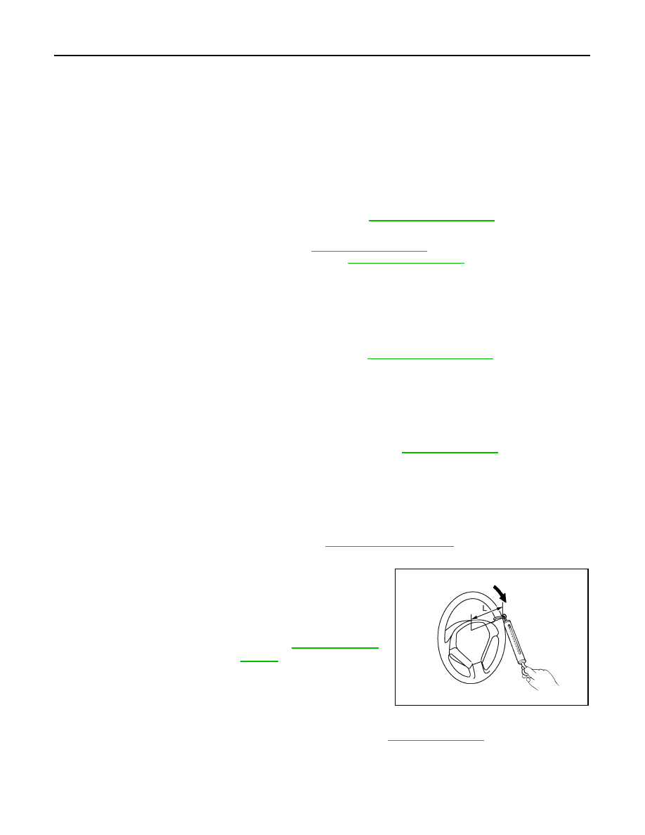
STEERING WHEEL TURNING FORCE

1. Park vehicle on a level and dry surface, set parking brake.
2. Tires need to be inflated normal pressure. Refer to 

WT-73, "Tire Air Pressure"

.

3. Start engine.
4. Check steering wheel turning force, using Tool, when steering

wheel has been turned 360

° from neutral position.

FRONT WHEEL TURNING ANGLE

1. Check front wheel turning angle after toe-in inspection. Refer to 

FSU-7, "Inspection"

.

Steering wheel axial end play

: Refer to 

ST-18, "Steering Wheel"

.

Steering wheel play

: Refer to 

ST-18, "Steering Wheel"

.

Tool number

:  —  (J-44372)

Steering wheel turning 
force

: Refer to 

ST-18, "Steering 

Wheel"

.

JSGIA0027ZZ

STEERING WHEEL

ST-7

< BASIC INSPECTION >

C

D

E

F

H

I

J

K

L

M

A

B

ST

N

O

P

2. Place front wheels on turning radius gauges and rear wheels on

stands, so that vehicle can be level.

3. Check the maximum inner and outer wheel turning angles for LH

and RH road wheels.

4. With the engine at idle, turn steering wheel from full left stop to

full right stop and measure the turning angles.

5. Check the following items when turning angle is outside of the

standard.

a. Check the neutral position of the rack stroke (L).

b. Check steering gear, steering column and front suspension

components for wear or damage if any of the turning angles are

different from the specified value. Replace components if any

conditions are outside of the standard.

NOTE:

Steering angles are not adjustable.

FAA0016D

Inner wheel (Angle: A)

: Refer to 

ST-18, "Steering 

Angle"

.

Outer wheel (Angle: B)

: Refer to 

ST-18, "Steering 

Angle"

.

SGIA0055E

Rack stroke in neutral 
position (L)

: Refer to 

ST-19, "Steering 

Gear"

.

SGIA0629J

ST-8

< BASIC INSPECTION >

STEERING COLUMN

STEERING COLUMN

Inspection

INFOID:0000000011280293

HOLE COVER SEAL, HOLE COVER AND LOWER SHAFT

Check each part of hole cover seal, hole cover and steering column and lower shaft for damage or other mal-

functions. Replace if necessary.

STEERING COLUMN

• Check each part of steering column for damage or other malfunctions. Replace entire steering column if any

parts are damaged.

• Measure the steering column length (with the steering wheel and airbag module installed) if vehicle has

been involved in a minor collision. Replace steering column if outside the specifications.

• Measure steering column rotating torque using suitable tool. Replace steering column if outside the stan-

dard.

• Check tilt and telescopic mechanism operating range (L

1

), (L

2

) as

shown.

Steering column length (with steering 
wheel and air bag module installed)

: Refer to

ST-18, "Steering Column"

.

Rotating torque

: Refer to 

ST-18, "Steering Column"

.

Tilt operating range (L

1

)

: Refer to 

ST-18, "Steering 

Column"

.

Telescopic operating range 
(L

2

)

: Refer to

ST-18, "Steering 

Column"

.

ALGIA0106ZZ

STEERING GEAR AND LINKAGE

ST-9

< BASIC INSPECTION >

C

D

E

F

H

I

J

K

L

M

A

B

ST

N

O

P

STEERING GEAR AND LINKAGE

Inspection

INFOID:0000000011280294

STEERING GEAR

• Check boot for cracks, and replace it if an abnormal condition is detected.

• Check gear housing for damage and scratches (inner wall). Replace if there are any abnormal conditions.

OUTER SOCKET AND INNER SOCKET

• Ball joint swinging torque

- Hook Tool at the measuring point and pull Tool. Make sure that

Tool reads the specified value when ball stud and inner socket start

to move. Replace outer socket or steering gear (inner socket) if

they are outside the standard.

• Ball joint rotating torque

- Make sure that the reading is within the following specified range

using suitable tool (A). Replace outer socket if the reading is out-

side the specification.

• Ball joint axial end play

- Apply an axial load of 490 N (50 kg, 111 lb) to ball stud. Measuring

the amount of stud movement using a dial gauge, make sure that

the value is within specification. Replace outer socket (A) and

inner socket (B) if the measured value is outside specification.

RACK SLIDING FORCE

1. Set the front wheels and tires to the straight-ahead position.
2. Remove the column hole cover. Refer to 

ST-12, "Exploded View"

.

3. Remove the lower cover seal. Refer to 

ST-12, "Exploded View"

.

4. Remove the joint retaining bolt and separate the steering column joint from the steering gear pinion shaft.

Refer to 

ST-12, "Exploded View"

.

CAUTION:

With the steering linkage disconnected, the spiral cable may snap by turning the steering wheel

beyond the limited number of turns. Secure the steering wheel.

Measuring point of outer socket (1)

: Ball stud upper side (A)

Measuring point of inner socket (2)

: Point (B)

Tool number

:  —  (J-44372)

Swinging torque : Refer to 

ST-19, "Steering Gear"

.

JPGIA0188ZZ

Rotating torque

: Refer to 

ST-19, "Steering Gear"

AWGIA0228ZZ

Axial end play

: Refer to 

ST-19, "Steering Gear"

.

JSGIA0109ZZ


Content   ..  1137  1138  1139  1140   ..