Content .. 1026 1027 1028 1029 ..
Nissan Rogue. Manual - part 1028
REAR SUSPENSION MEMBER
RSU-25
< UNIT REMOVAL AND INSTALLATION >
C
D
F
G
H
I
J
K
L
M
A
B
RSU
N
O
P
UNIT REMOVAL AND INSTALLATION
REAR SUSPENSION MEMBER
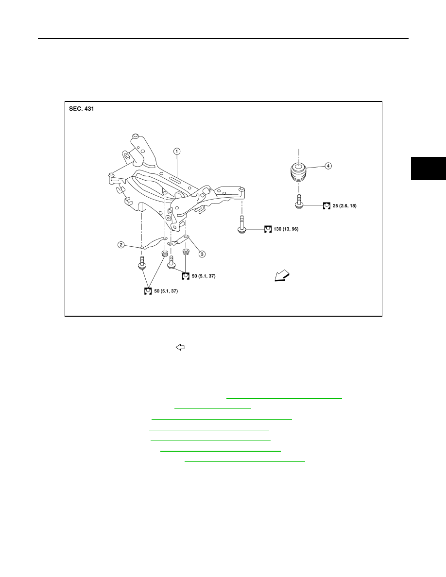
Exploded View
INFOID:0000000011276555
Removal and Installation - FWD
INFOID:0000000011276556
REMOVAL
1. Remove wheel and tires using power tool. Refer to
WT-67, "Removal and Installation"
2. Remove muffler assembly. Refer to
.
3. Remove coil spring. Refer to
RSU-8, "Removal and Installation - FWD"
4. Remove lower link. Refer to
RSU-19, "Removal and Installation"
.
5. Remove upper link. Refer to
RSU-21, "Removal and Installation"
.
6. Remove rear stabilizer.Refer to
RSU-23, "Removal and Installation"
7. Remove rear shock absorber. Refer to
RSU-15, "Removal and Installation"
8. Set suitable jack under rear suspension member.
9. Remove bolts from rear suspension member.
10. Slowly lower suitable jack and remove rear suspension member.
CAUTION:
Secure suspension assembly to a suitable jack while removing it.
INSPECTION AFTER REMOVAL
Check rear suspension member for deformation, cracks, or any other damage. Replace it if necessary.
INSTALLATION
Installation is in the reverse order of the removal.
1.
Rear suspension member
2.
Suspension member stay
(RH)
3.
Suspension member stay (LH)
4.
Bound bumper
Front
ALEIA0214ZZ