Content .. 1024 1025 1026 1027 ..
Nissan Rogue. Manual - part 1026
REAR SUSPENSION ARM
RSU-17
< REMOVAL AND INSTALLATION >
C
D
F
G
H
I
J
K
L
M
A
B
RSU
N
O
P
REAR SUSPENSION ARM
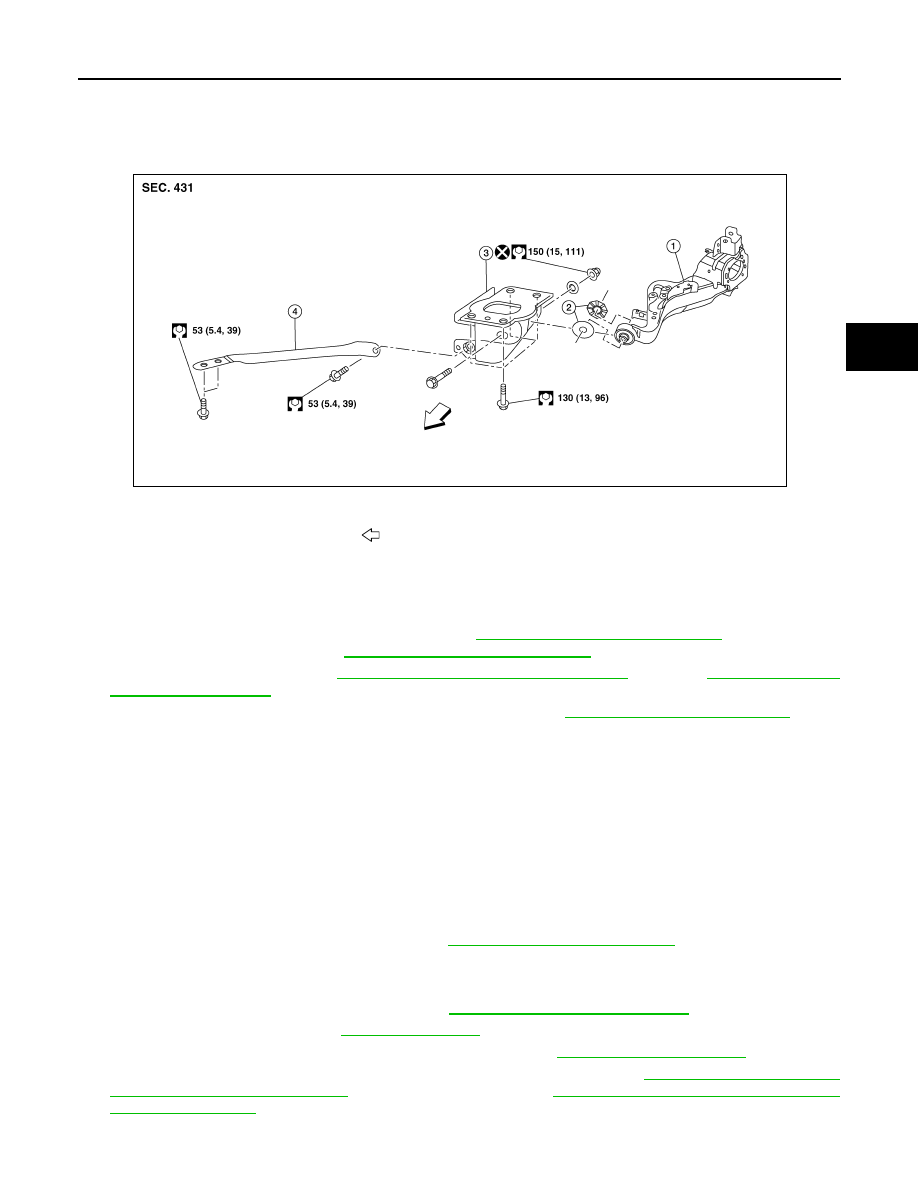
Exploded View
INFOID:0000000011276543
Removal and Installation
INFOID:0000000011276544
REMOVAL
1. Remove the wheel hub and bearing (FWD). Refer to
RAX-16, "Removal and Installation"
(FWD). Remove
the axle housing (AWD). Refer to
RAX-16, "Removal and Installation"
(AWD).
2. Remove the coil spring.Refer to
RSU-8, "Removal and Installation - FWD"
(AWD).
3. Separate the brake tube and hose from the rear suspension arm.
4. Remove the nut, bolt, rubber washer (LH/RH), and rear suspension arm.
INSPECTION AFTER REMOVAL
Visual Inspection
Check rear suspension arm and bushing for deformation, cracks or damage. Replace it if necessary.
INSTALLATION
Installation is in the reverse order of removal.
CAUTION:
• Do not reuse rear suspension arm nut.
• Verify that arm bushing stoppers are installed correctly with proper orientation.
• Align the matching marks made during removal when reusing the disc brake rotor.
• After installation, perform the air bleeding. Refer to
BR-16, "Bleeding Brake System"
.
• Perform the final tightening of the nuts and bolts under unladen conditions with the tires on level ground.
INSPECTION AFTER INSTALLATION
1. Adjust parking brake operation (stroke). Refer to
PB-4, "Inspection and Adjustment"
2. Check wheel alignment. Refer to
3. Adjust the neutral position of the steering angle sensor. Refer to
4. Perform the sensor initialize of the headlamp aiming control system. Refer to
IZE : Special Repair Requirement"
(HALOGEN HEADLAMP) or
EXL-221, "SENSOR INITIALIZE : Special
(LED HEADLAMP).
1.
Rear suspension arm
2.
Arm bushing stopper (LH/RH) 3.
Rear suspension arm bracket
4.
Rear suspension arm stay
Front
AWEIA0353ZZ