Nissan Rogue. Manual - part 7
AV-20
< SYSTEM DESCRIPTION >
[DISPLAY AUDIO]
DIAGNOSIS SYSTEM (AUDIO UNIT)
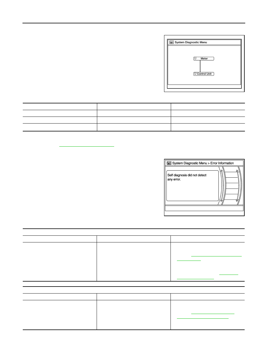
2. Self diagnosis screen is displayed. The bar graph visible in center of screen indicates progress of self
diagnosis.
3. Diagnosis results are displayed after the self diagnosis is com-
pleted. The unit names and the connection lines are color coded
according to the diagnostic results.
1: Control unit (audio unit) is displayed in red.
• Replace audio unit if Self Diagnosis did not run because control unit malfunction is indicated. The symptom is audio unit internal
error. Refer to
AV-67, "Removal and Installation"
.
• If multiple errors occur at the same time for a single unit, the screen switch colors are determined according to the following order
of priority: red > gray.
4. Comments of self diagnosis results can be viewed in the diagno-
sis result screen.
Audio Unit Self Diagnosis Results
AWNIA2630GB
Diagnosis results
Unit
Connection line
Normal
Green
Green
Connection malfunction
Gray
Yellow
Unit malfunction
1
Red
Green
JSNIA1870ZZ
Only Unit Part Is Displayed In Red
Screen switch
Description
Possible cause
Control unit
Malfunction is detected in audio unit power
supply and ground circuits.
• Audio unit power supply or ground cir-
cuits.
Refer to
.
• If no malfunction is detected in audio unit
power supply and ground circuits, re-
place audio unit. Refer to
.
A Connecting Cable Between Units Is Displayed In Yellow
Area with yellow connection lines
Description
Possible cause
Control unit
⇔ Meter
When one of the following is detected:
• malfunction is detected in combination
meter power supply and ground circuits.
• malfunction is detected in AV communi-
cation circuits between audio unit and
combination meter.
• Combination meter power supply or
ground circuits.
Refer to
.
• AV communication circuits between au-
dio unit and combination meter.