Nissan Rogue. Manual - part 8


  Index      Nissan     Nissan Rogue (2015 year) - Service and Repair Manual


Search            


Content   ..  6  7  8  9   ..


Nissan Rogue. Manual - part 8


AV-24

< SYSTEM DESCRIPTION >

[DISPLAY AUDIO]

DIAGNOSIS SYSTEM (AUDIO UNIT)

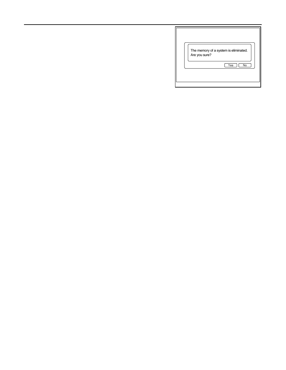
Deletes data stored from the audio unit.

JSNIA0155GB

AV

AUDIO UNIT

AV-25

< ECU DIAGNOSIS INFORMATION >

[DISPLAY AUDIO]

C

D

E

F

G

H

I

J

K

L

M

B

A

O

P

ECU DIAGNOSIS INFORMATION

AUDIO UNIT

Reference Value

INFOID:0000000011276744

TERMINAL LAYOUT

PHYSICAL VALUES

AWNIA3725ZZ

Terminal

(Wire color)

Description

Condition

Reference value

(Approx.)

+

Signal name

Input/

Output

Ignition 

switch

Operation

2

(W)

3

(P)

Sound signal front door 
speaker and front tweeter 
LH

Output

ON

Sound output

4

(GR)

5

(BR)

Sound signal rear door 
speaker LH

Output

ON

Sound output

7

(LG)

Ground Ignition power supply

Input

ON

Battery voltage

9

 (V)

8

(R)

Illumination control signal

Input

ON

Headlamps ON

Battery voltage

11

(G)

12

(V)

Sound signal front door 
speaker and front tweeter 
RH

Output

ON

Sound output

SKIB3609E

SKIB3609E

SKIB3609E

AV-26

< ECU DIAGNOSIS INFORMATION >

[DISPLAY AUDIO]

AUDIO UNIT

13

(LG)

14

(Y)

Sound signal rear door 
speaker RH

Output

ON

Sound output

18

(G)

Ground Vehicle speed signal

Input

ON

When vehicle speed is ap-
prox. 40 km/h (25 MPH)

19

(L)

Ground Battery power supply

Input

OFF

Battery voltage

20

(B)

Ground Ground

ON

0 V

21

(L)

Ground AUX jack audio signal LH

Input

ON

Received audio signal 
(AUX input)

22

(G)

Ground AUX jack audio signal RH

Input

ON

Received audio signal 
(AUX input)

23

(Y)

Ground

AUX ground

ON

0V

24

(Shield)

AUX signal shield

35

(W)

Ground ACC power supply

Input

ON

Battery voltage

36

(SB)

AV communication (H)

Input/

Output

37

(LG)

AV communication (L)

Input/

Output

39

(SB)

AV communication (H)

Input/

Output

40

(LG)

AV communication (L)

Input/

Output

41

(B)

Ground Camera ground

ON 

0 V

Terminal

(Wire color)

Description

Condition

Reference value

(Approx.)

+

Signal name

Input/

Output

Ignition 

switch

Operation

SKIB3609E

JSNIA0012GB

SKIB3609E

SKIB3609E

AV

AUDIO UNIT

AV-27

< ECU DIAGNOSIS INFORMATION >

[DISPLAY AUDIO]

C

D

E

F

G

H

I

J

K

L

M

B

A

O

P

42

(R)

Ground Camera power supply

Output

ON

Camera image displayed

6.0 V

Except for above

0 V

43

(W)

44

(Shield)

Camera image signal

Input

ON

Camera image displayed

45

(W)

47

(Shield)

Microphone signal

Input

ON

While speaking into micro-
phone. 

46

(B)

MIC VCC

Input

ON

52

(B)

Ground Camera detection

ON

0 V

58

(BR)

Ground Reverse signal

Input

ON

Selector lever in R (re-
verse)

Battery voltage

Selector lever in any posi-
tion other than R (reverse)

0 V

61

(R)

V BUS signal

62

(W)

USB D

− signal

63

(G)

USB D+ signal

65

(B)

USB ground

66

(Shield)

USB shield

67

(B)

Ground Antenna amp. ON signal

Output

ON

Audio unit ON, FM-AM se-
lected.

Battery voltage

68

(B)

Ground AM/FM antenna signal

Input

ON

Audio unit ON, FM-AM se-
lected.

5.0 V

    69
(Shield)

AM/FM antenna shield

72

(B)

Ground Satellite antenna signal

Input

ON

Audio unit ON, XM select-
ed.

5.0 V

73

(Shield)

Satellite antenna shield

Terminal

(Wire color)

Description

Condition

Reference value

(Approx.)

+

Signal name

Input/

Output

Ignition 

switch

Operation

SKIB2251J

SKIB3609E


Content   ..  6  7  8  9   ..