Nissan Maxima. Manual - part 859
MWI
COMBINATION METER
MWI-51
< ECU DIAGNOSIS INFORMATION >
C
D
E
F
G
H
I
J
K
L
M
B
A
O
P
DTC Index
INFOID:0000000010049601
NOTE:
“TIME” indicates the following.
• 0: Indicates that a malfunction is detected at present.
• 1-63: Indicates that a malfunction was detected in the past. (Displays number of ignition switch OFF
→ ON
cycles after malfunction is detected. Self-diagnosis result is erased when “63” is exceeded.)
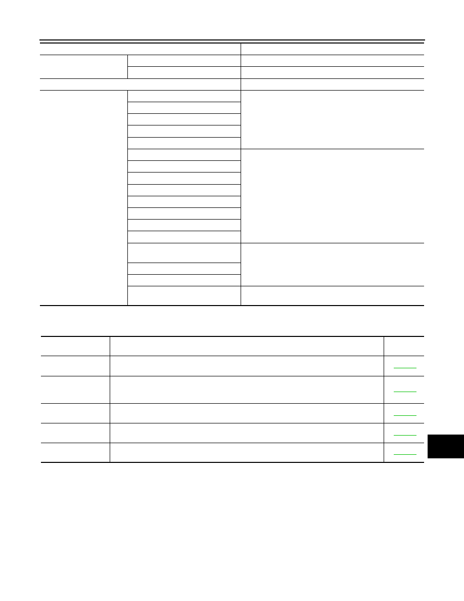
Segment LCD
Odometer
Freeze current indication.
CVT position
Display turns off.
Buzzer
Buzzer turns off.
Warning lamp/indicator lamp
ABS warning lamp
Lamp turns on when communication is lost.
Brake warning lamp
TCS/VDC OFF indicator lamp
SLIP indicator lamp
Malfunction indicator lamp
CVT warning lamp
Lamp turns off when communication is lost.
Oil pressure warning lamp
Master warning lamp
Air bag warning lamp
High beam indicator
Turn signal indicator lamp
CRUISE indicator lamp
Intelligent Key system warning lamp
Driver and passenger seat belt warn-
ing lamp
Lamp turns off when disconnected.
Charge warning lamp
Security indicator lamp
Low tire pressure warning lamp
Lamp will flash every second for 1 minute and then stay on con-
tinuously thereafter.
Function
Specifications
CONSULT display
Malfunction
Reference
page
CAN COMM CIRCUIT
[U1000]
When combination meter is not transmitting or receiving CAN communication signal for 2 sec-
onds or more.
CONTROL UNIT
(CAN)
[U1010]
When detecting error during the initial diagnosis of the CAN controller of combination meter.
VEHICLE SPEED
[B2205]
The abnormal vehicle speed signal is input from the ABS actuator and electric unit (control unit)
for 2 seconds or more.
ENGINE SPEED
[B2267]
If ECM continuously transmits abnormal engine speed signals for 2 seconds or more.
WATER TEMP
[B2268]
If ECM continuously transmits abnormal engine coolant temperature signals for 60 secosnds or
more.