Nissan Maxima. Manual - part 609
EXL-178
< SYSTEM DESCRIPTION >
[HALOGEN TYPE]
AUTO LIGHT SYSTEM
AUTO LIGHT SYSTEM
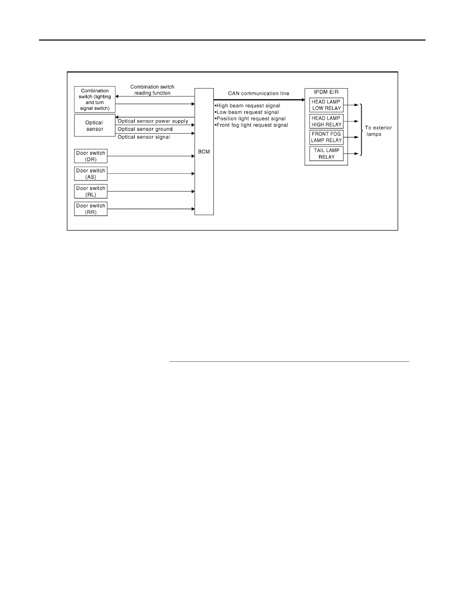
System Diagram
INFOID:0000000010051029
System Description
INFOID:0000000010051030
• BCM (Body Control Module) controls auto light operation according to signals from optical sensor, lighting
switch and ignition switch.
• IPDM E/R (Intelligent Power Distribution Module Engine Room) operates parking, license plate, tail, front fog
lamps and headlamps according to CAN communication signals from BCM.
• Optical sensor detects ambient brightness of 800 to 2,500 lux, converts light (lux) to voltage, and then sends
the optical sensor signal to BCM.
OUTLINE
The auto light control system has an optical sensor that detects outside brightness.
When the lighting switch is in AUTO position, it automatically turns ON/OFF the parking, license plate, tail,
front fog lamps and headlamps in accordance with the ambient light. Sensitivity can be adjusted in four steps.
For the details of the setting, refer to
EXL-191, "HEADLAMP : CONSULT Function (BCM - HEAD LAMP)"
ABLIA2703GB