Nissan Maxima. Manual - part 610
EXL-182
< SYSTEM DESCRIPTION >
[HALOGEN TYPE]
TURN SIGNAL AND HAZARD WARNING LAMPS
TURN SIGNAL AND HAZARD WARNING LAMPS
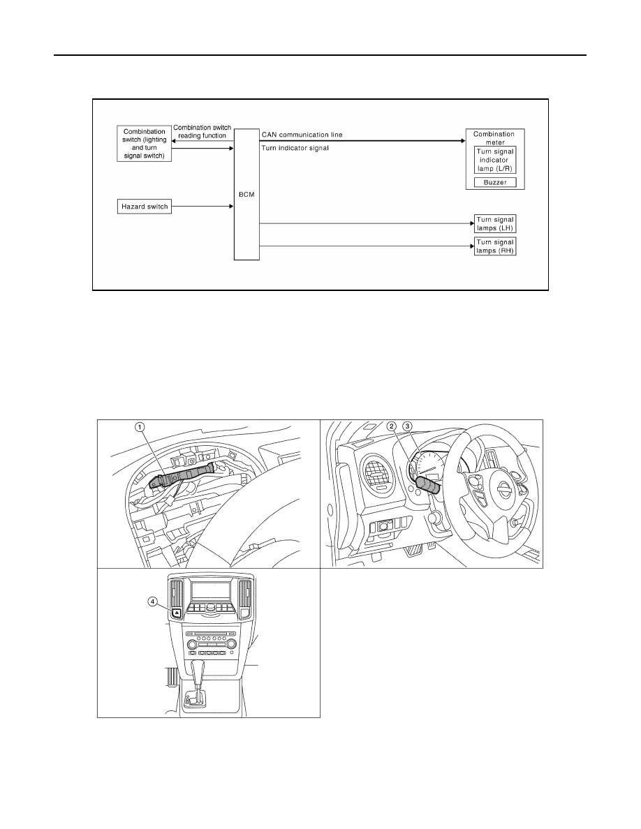
System Diagram
INFOID:0000000010051037
System Description
INFOID:0000000010051038
• BCM (Body Control Module) controls turn signal lamp (RH and LH) and hazard warning lamp operation.
• Combination meter operates turn signal indicator (RH and LH) according to CAN communication signals
from BCM.
Component Parts Location
INFOID:0000000010051039
ABLIA2705GB
1.
BCM M16, M17, M18, M19 (view with
combination meter removed)
2.
Combination switch (lighting and turn
signal switch) M28
3.
Combination meter M24
4.
Hazard switch M54
AWLIA1635ZZ