Nissan Maxima. Manual - part 604
EXL-158
< REMOVAL AND INSTALLATION >
[XENON TYPE]
OPTICAL SENSOR
OPTICAL SENSOR
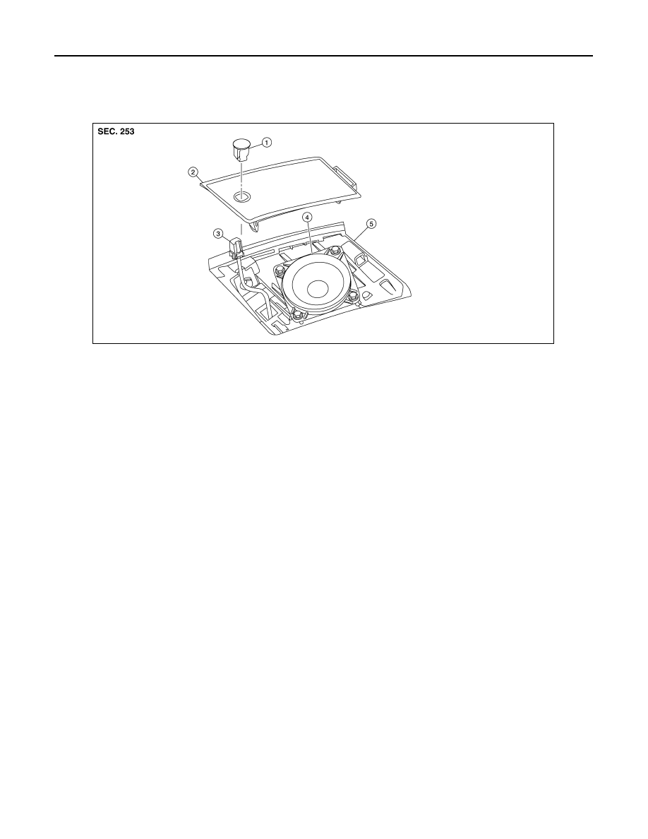
Exploded View
INFOID:0000000009465279
Removal and Installation
INFOID:0000000009465280
CAUTION:
Whenever a suitable tool is used, always wrap a cloth around the end of the tool to protect compo-
nents from damage.
REMOVAL
1. Carefully remove the LH front tweeter speaker grille using a suitable tool.
2. Insert a suitable tool between the optical sensor and the LH front tweeter speaker grille. Lift the optical
sensor upward.
3. Disconnect the harness connector from the optical sensor and remove.
INSTALLATION
Installation is in the reverse order of removal.
1.
Optical sensor
2.
LH front tweeter speaker grille
3.
Optical sensor harness connector
4.
LH front tweeter speaker
5.
Instrument panel
ALLIA0900ZZ