Nissan Maxima. Manual - part 559


  Index      Nissan     Nissan Maxima (2009-2014 year) - Service and Repair Manual


Search            


Content   ..  557  558  559  560   ..


Nissan Maxima. Manual - part 559


EM-124

< UNIT DISASSEMBLY AND ASSEMBLY >

CYLINDER BLOCK

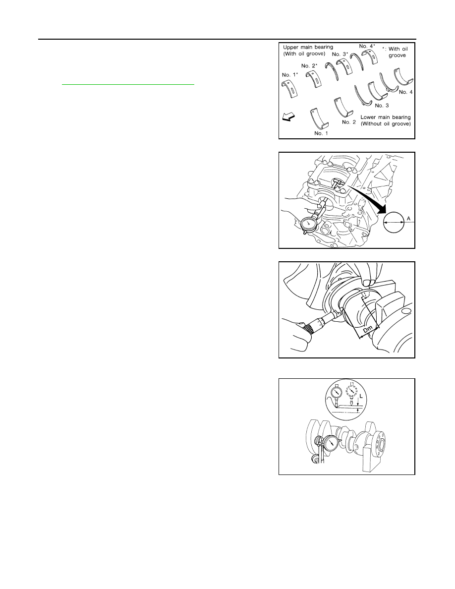
1. Set the main bearings in their proper positions on the cylinder

block and the main bearing cap.

2. Install the main bearing caps and bearing beam to the cylinder

block. Tighten all bolts in the numerical order as specified. Refer

to 

EM-107, "Disassembly and Assembly"

.

3. Measure the inner diameters "A" of each main bearing as

shown.

4. Measure the outer diameters "Dm" of each crankshaft main jour-

nal as shown.

5. Calculate the main bearing clearance.

Main bearing clearance = "A" - "Dm"

• If it exceeds the limit, replace the bearing.

• If clearance cannot be adjusted using any standard bearing

grade, grind crankshaft journal and use an undersized bear-

ing.

• When grinding the crankshaft journal, confirm that the "L"

dimension in the fillet role is more than the specified limit.

6. If the crankshaft or the cylinder block is replaced with a new one, select thickness of the main bearings as

follows:

SEM175F

SEM845E

Standard

: 0.012 - 0.022 mm (0.0005 - 0.0009 in)

Limit

: 0.065 mm (0.0026 in)

AEM033

"L" 

: 0.10 mm (0.0039 in)

SEM964

CYLINDER BLOCK

EM-125

< UNIT DISASSEMBLY AND ASSEMBLY >

C

D

E

F

G

H

I

J

K

L

M

A

EM

N

P

O

a. The grade number of each cylinder block main journal is

punched on the respective cylinder block. These numbers are

punched in either Arabic or Roman numerals. If measured diam-

eter is out of the grade punched, decide suitable grade from

available main bearings.

b. The grade number of each crankshaft main journal is punched

on the crankshaft end. These numbers are punched in either

Arabic or Roman numerals. If measured diameter is out of grade

punched, decide the suitable grade from available main bear-

ings.

c. Select the main bearing suitable thickness according to the following table:

SEM756G

SEM452G

PBIC0814E

EM-126

< UNIT DISASSEMBLY AND ASSEMBLY >

CYLINDER BLOCK

Connecting Rod Bearing (Big End)

1. Install the connecting rod bearing to the connecting rod and cap.
2. Install the connecting rod cap to the connecting rod. Tighten to specification. Refer to 

EM-107, "Disassem-

bly and Assembly"

.

3. Measure the inner diameter "C" of each connecting rod (big end)

as shown.

4. Measure the outer diameter "Dp" of each crankshaft pin journal.
5. Calculate the connecting rod bearing clearance.

Connecting rod bearing clearance = C - Dp

6. If the calculated clearance exceeds the specified limit, replace

the bearings.

7. If the clearance cannot be adjusted within the standard of any

bearing, grind the crankshaft journal and use undersized bear-

ings.

8. If the crankshaft is replaced with a new one, select the connect-

ing rod bearings according to the following table:

Connecting Rod Bearing Grade Number (Identification

Color)

These numbers are punched in either Arabic or Roman numer-

als.

Method B (Using Plastigage)

• Remove oil and dust on the crankshaft pin and the surfaces of

each bearing completely. 

• Cut a Plastigage slightly shorter than the bearing width, and place

it in crankshaft axial direction, avoiding oil holes.

• Install the connecting rod bearings to the connecting rod cap, and

tighten the connecting rod nuts to the specified torque. 

CAUTION:

Do not rotate the crankshaft.

• Remove the connecting rod cap and bearings, and using the scale

on the Plastigage bag, measure the Plastigage width. 

NOTE:

The procedure when the measured value exceeds the repair limit

is same as that described in "Method A (Using Bore Gauge and Micrometer)".

DRIVE PLATE RUNOUT 

AEM027

Standard

: 0.020 - 0.045 mm (0.0008 - 0.0018 in)

Limit

: 0.070 mm (0.0028 in)

AEM034

Crankshaft pin journal grade 

number

Connecting rod bearing grade 

number

                          0

                    0 (black)

                          1

                    1 (brown)

                          2

                    2 (green)

SEM452G

SEM142

CYLINDER BLOCK

EM-127

< UNIT DISASSEMBLY AND ASSEMBLY >

C

D

E

F

G

H

I

J

K

L

M

A

EM

N

P

O

Use a suitable tool to measure the runout (Total Indicator Reading)

as shown.

CAUTION:

• The signal plate is built into the drive assembly. Be careful not

to damage the signal plate, particularly the teeth.

• Check the drive plate and signal plate for deformation or

cracks.

• Keep all magnetized objects away from the signal plate, par-

ticularly the teeth.

OIL JET

• Check nozzle for deformation and damage.

• Blow compressed air from nozzle, and check for clogs.

• If it is not operating properly, replace oil jet.

OIL JET RELIEF VALVE

• Using a clean plastic stick, press check valve in oil jet relief valve.

Make sure that valve moves smoothly with proper reaction force.

• If it is not operating properly, replace oil jet relief valve.

Dowel Pin Alignment

INFOID:0000000009466053

REMOVAL

1. Use suitable tool to lock the drive plate and match mark (A) the

drive plate before removing the bolts.

CAUTION:

Do not damage the ring gear teeth, or the signal plate teeth

behind the ring gear.

Drive plate torque converter 
surface

: less than 0.35 mm 
(.0138 in)

Ring gear

: less than 0.5 mm 
(.0197 in)

SEM849EB

SEM760G

EMU0468D

ALBIA0522ZZ


Content   ..  557  558  559  560   ..