Nissan Maxima. Manual - part 557


  Index      Nissan     Nissan Maxima (2009-2014 year) - Service and Repair Manual


Search            


Content   ..  555  556  557  558   ..


Nissan Maxima. Manual - part 557


EM-116

< UNIT DISASSEMBLY AND ASSEMBLY >

CYLINDER BLOCK

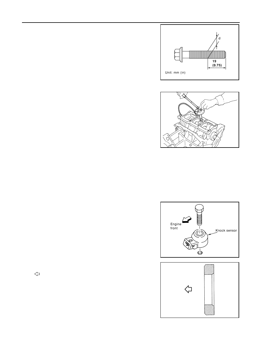
15. Check the connecting rod cap bolts before reusing, then install

in their original position in the connecting rod. The bolts should

screw in smoothly by hand.

• Measure the outer diameter of the connecting rod cap bolt as

shown.

16. Tighten the connecting rod nuts in two stages using Tool:

CAUTION:

Always use either an angle wrench or protractor. Avoid

tightening based on visual check alone.

• Apply engine oil to the threads and seats of the connecting rod

bolts and nuts. 

• After tightening the nuts, make sure that the crankshaft rotates

smoothly. 

• Check the connecting rod side clearance. If beyond the limit, replace the connecting rod and/or crank-

shaft.

17. Install the baffle plate to the main bearing beam.
18. Install the knock sensor.

• Make sure that there is no foreign material on the cylinder

block mating surface and the back surface of the knock sen-

sor. 

• Install the knock sensor with the connector facing the rear of

the engine. 

• Do not tighten the bolts while holding the connector.   

• Make sure that the knock sensor does not interfere with other

parts.

CAUTION:

If any impact by dropping occurs to the knock sensor,

replace it with new one.

19. Install the pilot converter with it’s chamfer facing crankshaft as

shown.

: Crankshaft side

Outer diameter "d" of the connecting rod bolt
Standard

: 7.90 - 8.00 mm (0.3110 - 0.3150 in)

Limit

: 7.75 mm (0.3051 in)

SEM538G

Stage 1

: 19 - 21 N·m (1.9 - 2.1 kg-m, 14 - 15 ft-lb)

Stage 2

: 90

° - 95° degrees clockwise

Tool number

: KV10112100 (BT-8653-A)

Connecting rod side clearance:
Standard

: 0.20 - 0.35 mm (0.0079 - 0.0138 in)

Limit

: 0.40 mm (0.0157 in)

SEM953E

PBIC0810E

JPBIA0210ZZ

CYLINDER BLOCK

EM-117

< UNIT DISASSEMBLY AND ASSEMBLY >

C

D

E

F

G

H

I

J

K

L

M

A

EM

N

P

O

20. Install the drive plate. Refer to 

EM-127, "Dowel Pin Alignment"

.

21. Install the cylinder head. Refer to 

EM-90, "Removal and Installation"

.

22. Install the timing chain. Refer to 

EM-64, "Removal and Installation"

.

23. Install the oil pan. Refer to 

EM-37, "Removal and Installation (Upper Oil Pan)"

.

24. Remove the engine from the stand and install the engine assembly into the vehicle. Refer to 

EM-103,

"Removal and Installation"

.

25. Assembly of the remaining parts is in the reverse order of disassembly.

CAUTION:

Do not fill the engine with oil for at least 30 minutes after the components are installed to allow the

sealant to cure.

INSPECTION AFTER INSTALLATION

• Before starting engine, check oil/fluid levels including engine coolant and engine oil. If less than required

quantity, fill to the specified level. Refer to 

MA-15, "FOR USA AND CANADA : Fluids and Lubricants"

 (United

States and Canada) or 

MA-16, "FOR MEXICO : Fluids and Lubricants"

 (Mexico).

• Use procedure below to check for fuel leakage.

• Turn ignition switch ON (with engine stopped). With fuel pressure applied to fuel piping, check for fuel leak-

age at connection points.

• Start engine. With engine speed increased, check again for fuel leakage at connection points.

• Run engine to check for unusual noise and vibration.

NOTE:

If hydraulic pressure inside timing chain tensioner drops after removal and installation, slack in the guide

may generate a pounding noise during and just after engine start. However, this is normal. Noise will stop

after hydraulic pressure rises.

• Warm up engine thoroughly to make sure there is no leakage of fuel, exhaust gas, or any oils/fluids including

engine oil and engine coolant.

• Bleed air from passages in lines and hoses, such as in cooling system.

• After cooling down engine, again check oil/fluid levels including engine oil and engine coolant. Refill to spec-

ified level, if necessary.

• Summary of the inspection items:

*Power steering fluid, brake fluid, etc.

Inspection

INFOID:0000000009466052

PISTON AND PISTON PIN CLEARANCE

Inner Diameter of Piston Pin Hole

Item

Before starting engine

Engine running

After engine stopped

Engine coolant

Level

Leakage

Level

Engine oil

Level

Leakage

Level

Transmission/
transaxle fluid 

A/T and CVT Models

Leakage

Level/Leakage

Leakage

M/T Models

Level/Leakage

Leakage

Level/Leakage

Other oils and fluids*

Level

Leakage

Level

Fuel

Leakage

Leakage

Leakage

Exhaust gas

Leakage

EM-118

< UNIT DISASSEMBLY AND ASSEMBLY >

CYLINDER BLOCK

• Measure the inner diameter of piston pin hole "dp".

Outer Diameter of Piston Pin

• Measure outer diameter of piston pin "Dp".

: Engine front

• Piston Grade No. (A)

• Piston front mark (B)

• Oil hole (C)

• Connecting rod front mark (D)

• Cylinder No. (E)

• Pin Grade No. (F)

Piston and Piston Pin Interference Fit

Standard Interference Fit = "Dp" – "dp"

• If clearance exceeds specification, replace either or both the piston/piston pin assembly and connecting rod

assembly with reference to specification of each part.

PISTON RING SIDE CLEARANCE

• Measure side clearance of piston ring and piston ring groove with

feeler gauge.

Standard diameter "dp"
Grade No. 0

: 21.993 – 21.999 mm (0.8659 – 0.8661 in)

Grade No. 1

: 21.999 – 22.005 mm (0.8661 – 0.8663 in)

AEM023

Standard diameter "Dp"
Grade No. 0

: 21.989 – 21.995 mm (0.8657 – 0.8659 in)

Grade No. 1

: 21.995 – 22.001 mm (0.8659 – 0.8662 in)

AEM024

AWBIA0027ZZ

Standard

: 0.002 – 0.010 mm (0.0001 – 0.0004 in)

Standard Side Clearance
Top ring

: 0.045 - 0.080 mm (0.0018 - 0.0031 in)

2nd ring

: 0.030 - 0.070 mm (0.0012 - 0.0028 in)

Oil ring

: 0.045 - 0.125 mm (0.0018 - 0.0049 in)

Maximum Limit
Top ring

: 0.11 mm (0.0043 in)

SEM024AA

CYLINDER BLOCK

EM-119

< UNIT DISASSEMBLY AND ASSEMBLY >

C

D

E

F

G

H

I

J

K

L

M

A

EM

N

P

O

• If out of specification, replace piston ring assembly. If clearance exceeds maximum limit with new rings,

replace piston

PISTON RING END GAP

• Insert piston ring until it is in the middle of the cylinder bore and

measure the end gap.

• If out of specification, replace piston ring. 

CONNECTING ROD BEND AND TORSION

• If it exceeds the limit, replace connecting rod assembly.

CONNECTING ROD BEARING HOUSING DIAMETER (BIG END)

2nd ring

: 0.1 mm (0.004 in)

Oil ring

: —

Standard
Top ring

: 0.23 - 0.28 mm (0.0091 - 0.0110 in)

2nd ring

: 0.33 - 0.43 mm (0.0130 - 0.0169 in)

Oil ring

: 0.20 - 0.45 mm (0.0079 - 0.0177 in)

Limit:
Top ring

: 0.50 mm (0.0197 in)

2nd ring

: 0.62 mm (0.0244 in)

Oil ring

: 0.80 mm (0.0315 in)

SEM599A

Bend

: Limit 0.15 mm (0.0059 in) per 100 mm 
(3.94 in) length

Torsion

: Limit 0.30 mm (0.0118 in) per 100 mm 
(3.94 in) length

SEM038F

SEM003F


Content   ..  555  556  557  558   ..