Nissan Maxima. Manual - part 555


  Index      Nissan     Nissan Maxima (2009-2014 year) - Service and Repair Manual


Search            


Content   ..  553  554  555  556   ..


Nissan Maxima. Manual - part 555


EM-108

< UNIT DISASSEMBLY AND ASSEMBLY >

CYLINDER BLOCK

CAUTION:

• Apply new engine oil to parts as marked in illustrations before installation.

• Place removed parts such as bearings and bearing caps in their proper order and direction.

• When installing the connecting rod nuts, and main bearing cap bolts, apply new engine oil to the

threads and mating surfaces

• Do not allow any magnetic materials to contact the signal plate teeth on the drive plate.

DISASSEMBLY

1. Remove the engine assembly. Refer to 

EM-103, "Removal and Installation"

.

2. Remove the crankshaft pulley.

• Use a suitable tool to prevent the crankshaft from turning.

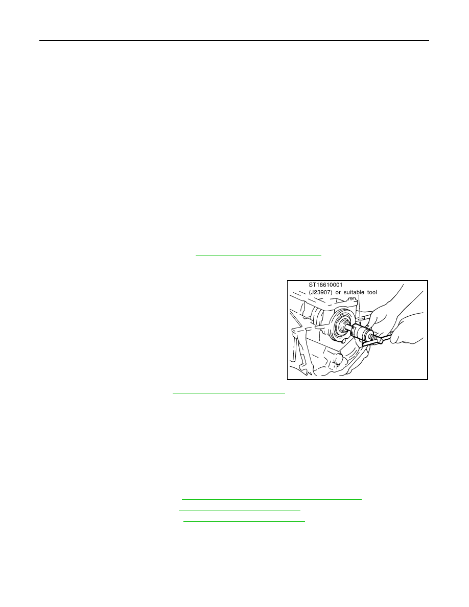
3. Remove pilot converter using Tool.

4. Remove the drive plate. Refer to 

EM-127, "Dowel Pin Alignment"

.

5. Install the engine on engine stand.

CAUTION:

Use an engine stand that has a load capacity [approximately 240kg (529) or more] large enough for

supporting the engine weight.

Before removing the hanging chains, make sure the engine stand is stable and there is no risk of

overturning.

6. Remove the knock sensor.

CAUTION:

Carefully handle sensor to avoid shocking it.

7. Drain the engine of all coolant and oil.
8. Remove the upper oil pan. Refer to 

EM-37, "Removal and Installation (Upper Oil Pan)"

.

9. Remove the timing chain. Refer to 

EM-64, "Removal and Installation"

.

10. Remove the cylinder head. Refer to 

EM-90, "Removal and Installation"

.

1.

Reinforcement plate

2.

Drive plate 

3.

Rear oil seal retainer

4.

Rear oil seal

5.

Sub harness

6.

Knock sensor 

7.

Cylinder block

8.

Thrust bearing (upper)

9.

Main bearing (upper)

10. Crankshaft

11. Crankshaft key

12. Thrust bearing (lower)

13. Main bearing (lower)

14. Main bearing cap

15. Main bearing cap bolt

16. Main bearing beam

17. Baffle plate

18. Connecting rod bolt

19. Connecting rod bearing cap

20. Connecting rod bearing

21. Connecting rod

22. Snap ring

23. Piston pin

24. Piston

25. Oil ring

26. Second ring

27. Top ring

28. Pilot converter

29. Oil jet

30. Gasket (for Canada)

31. Cylinder block heater (for Canada)

A.

Crankshaft side

B.

Chamfered

C.

Refer to INSTALLATION

D.

Front mark

Tool number

: ST16610001 (J-23907)

SEM005G

CYLINDER BLOCK

EM-109

< UNIT DISASSEMBLY AND ASSEMBLY >

C

D

E

F

G

H

I

J

K

L

M

A

EM

N

P

O

11. Cut away liquid gasket and remove rear oil seal retainer using

Tool. Refer to 

EM-4, "Precaution for Liquid Gasket"

.

CAUTION:

• Be careful not to damage mounting surface.

• If rear oil seal retainer is removed, replace it with a new

one.

NOTE:

Rear oil seal and retainer form a single part and are replaced as

an assembly.

12. Remove the piston and connecting rod assemblies.
a. Position the crankshaft pin corresponding to the connecting rod

to be removed onto the bottom dead center. 

b. Remove the connecting rod cap. 
c. Using a hammer handle or similar tool, push the piston and con-

necting rod assembly out to the cylinder head side. 

• Before removing the piston and connecting rod assembly,

check the connecting rod side clearance. Refer to 

EM-139,

"Connecting Rod Bearing"

.

13. Remove the connecting rod bearings. 

CAUTION:

• When removing the connecting rod side bearings, note the installation position. Keep them in

the correct order.

14. Remove the piston rings from the piston. 

• Use a piston ring expander.

CAUTION:

• When removing the piston rings, be careful not to damage

the piston. Do not expand the rings excessively.

• Be careful to mark the rings if they are to be reused so

they are installed in their original position.

• Before removing the piston rings, check the piston ring side clear-

ance. Refer to 

EM-117, "Inspection"

.

15. Remove the piston from the connecting rod as follows. 
a. Using a snap ring pliers, remove the snap ring.

CAUTION:

Do not reuse snap rings, always replace with new ones.

Tool number

: KV10111100 (J-37228)

SEM830E

PBIC0086E

PBIC0087E

PBIC0260E

EM-110

< UNIT DISASSEMBLY AND ASSEMBLY >

CYLINDER BLOCK

b. Heat the pistons to 60

° - 70°C (140° - 158°F).

WARNING:

Pistons contain heat. When working, wear protective equip-

ment to avoid getting burned.

c.

Push out the piston pin with a suitable tool, with an outer diame-

ter approximately 20 mm (0.8 in).

16. Remove the baffle plate from the main bearing beam.
17. Loosen the bolts in the reverse order as shown and remove the

main bearing beam, bearing caps and crankshaft. 

• Before loosening the main bearing cap bolts, measure the

crankshaft side clearance.

Refer to 

EM-117, "Inspection"

.

18. Remove the oil jets and dowel pins.
19. Remove the main bearings and thrust bearings from the cylinder

block and main bearing caps.

• When removing them, note the direction and position. Keep

them in the correct order for installation. 

ASSEMBLY

1. Blow out the coolant and oil passages and cylinder bore to remove any foreign materials.

CAUTION:

Use goggles to protect your eyes.

2. Apply liquid gasket and install each plug into the cylinder block.

• Use Genuine Silicone RTV Sealant or equivalent. Refer to 

GI-21, "Recommended Chemical Products

and Sealants"

.

CAUTION:

• Installation should be done within 5 minutes after applying liquid gasket.

SEM965A

PBIC0262E

: Engine front

AWBIA1394ZZ

PBIC0898E

CYLINDER BLOCK

EM-111

< UNIT DISASSEMBLY AND ASSEMBLY >

C

D

E

F

G

H

I

J

K

L

M

A

EM

N

P

O

• Do not fill the engine with oil for at least 30 minutes after the components are installed to allow

the sealant to cure.

3. Install the oil jets.

• Insert the oil jet dowel pin into the cylinder block dowel pin

hole, and tighten the bolts.

4. Install the main bearings and the thrust bearings.
a. Remove dust, dirt, and oil on the bearing mating surfaces of the

cylinder block and the main bearing cap.

b. Install the thrust bearings to both sides of the No. 3 journal hous-

ing on the cylinder block and the main bearing cap.

• Install the thrust bearings with the oil groove facing the crank-

shaft arm (outside).

• Install bearing with a projection on one end on cylinder block

and bearing with a projection at center on cap. Align each pro-

jection with mating notch.

5. Set the upper main bearings in their proper positions on the cyl-

inder block.

• Confirm the correct main bearings are used. Refer to 

EM-117,

"Inspection"

.

6. Instructions for the re-use of the main bearing cap bolts.

• A plastic zone tightening method is used for tightening the

main bearing cap bolts. Measure d1 and d2 as shown. 

• For d2, select the minimum diameter in the measuring area.

• If the difference between d1 and d2 exceeds the limit, replace

the bolts for assembly. 

PBIC0898E

PBIC0807E

SEM175F

Limit (d1 - d2)

: 0.11 mm (0.0043 in)

SEM177F


Content   ..  553  554  555  556   ..