Nissan Maxima. Manual - part 560


  Index      Nissan     Nissan Maxima (2009-2014 year) - Service and Repair Manual


Search            


Content   ..  558  559  560  561   ..


Nissan Maxima. Manual - part 560


EM-128

< UNIT DISASSEMBLY AND ASSEMBLY >

CYLINDER BLOCK

2. Remove drive plate.

• Loosen the drive plate in a diagonal order.

CAUTION:

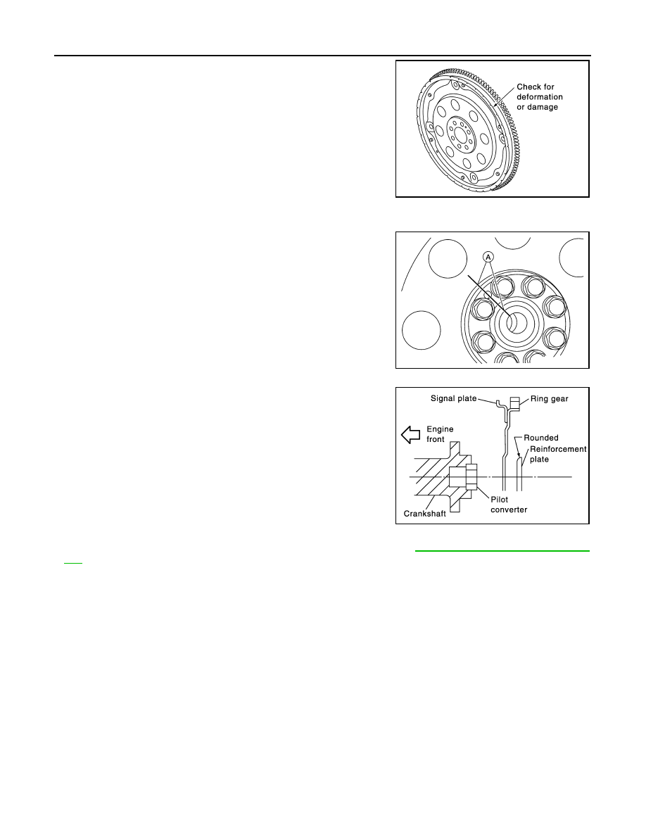
• Do not place drive plate with signal plate facing down.

• When handling the signal plate, take care not to damage

or scratch it.

• Handle the signal plate in a manner that prevents it from

becoming magnetized.

INSTALLATION 

Installation is in the reverse order of removal.

• When installing the drive plate to the crankshaft, use the match

mark (A) as shown to correctly align the crankshaft side dowel pin

to the drive plate side dowel pin hole.

• Install the drive plate and the reinforcement plate in the direction

as shown.

• Tighten the drive plate bolts in a diagonal pattern in two steps. Refer to 

EM-107, "Disassembly and Assem-

bly"

.

- Use a suitable tool to lock the drive plate.

SEM760G

ALBIA0522ZZ

PBIC0910E

SERVICE DATA AND SPECIFICATIONS (SDS)

EM-129

< SERVICE DATA AND SPECIFICATIONS (SDS) 

C

D

E

F

G

H

I

J

K

L

M

A

EM

N

P

O

SERVICE DATA AND SPECIFICATIONS (SDS)

SERVICE DATA AND SPECIFICATIONS (SDS)

General Specification

INFOID:0000000009466054

GENERAL SPECIFICATIONS

Drive Belt

INFOID:0000000009466055

DRIVE BELT

Cylinder arrangement

V-6

Displacement cm

3

 (cu in)

3,498 (213.45)

Bore and stroke mm (in)

95.5 x 81.4 (3.760 x 3.205)

Valve arrangement

DOHC

Firing order

1-2-3-4-5-6

Number of piston rings

Compression

2

Oil

1

Number of main bearings

4

Compression ratio

10.6:1

Compression pressure                                   
kPa (kg/cm

2

, psi)/300 rpm

Standard

1,275 (13.0, 185)

Minimum

981 (10.0, 142)

Differential limit between cylinders

98 (1.0, 14)

Cylinder number

Valve timing
(Valve timing control - “OFF”)

Unit: degree

a

b

c

d

e

f

240

240

−10

70

10

50

SEM713A

PBIC0187E

Tension of drive belt

Drive belt tension is not necessary, as it is automatically adjusted by drive belt auto-tensioner.

EM-130

< SERVICE DATA AND SPECIFICATIONS (SDS) 

SERVICE DATA AND SPECIFICATIONS (SDS)

Spark Plug

INFOID:0000000009466056

SPARK PLUG

Unit: mm (in)

*: Always check with the Parts Department for the latest parts information.

Intake Manifold 

INFOID:0000000009466057

INTAKE MANIFOLD

Unit: mm (in)

Exhaust Manifold

INFOID:0000000009466058

EXHAUST MANIFOLD

Unit: mm (in)

Camshaft

INFOID:0000000009466059

CAMSHAFT

Unit: mm (in)

Make

DENSO

Standard type*

FXE22HR11

Gap

Standard

1.1 (0.043)

Limit

1.4 (0.055)

Items

                                Limit

Surface distortion

Intake manifold

0.1 (0.004)

Items

                                Limit

Surface distortion

Exhaust manifold

0.3 (0.012)

Items

Standard

Limit

Camshaft journal oil clearance

No. 1

0.045 - 0.086 (0.0018 - 0.0034)

0.15 (0.0059)

No. 2, 3, 4

0.035 - 0.076 (0.0014 - 0.0030)

Camshaft bracket inner diameter

No. 1

26.000 - 26.021 (1.0236 - 1.0244)

No. 2, 3, 4

23.500 - 23.521 (0.9252 - 0.9260)

Camshaft journal diameter

No. 1

25.935 - 25.955 (1.0211 - 1.0218)

No. 2, 3, 4

23.445 - 23.465 (0.9230 - 0.9238)

Camshaft end play

0.115 - 0.188 (0.0045 - 0.0074)

0.24 (0.0094)

Camshaft cam height “A”

Intake

45.475 - 45.665 (1.7904 - 1.7978)

0.2 (0.008)*

1

Exhaust

45.485 - 45.675 (1.7907 - 1.7982)

0.2 (0.008)*

1

Camshaft runout [TIR*

2

]

Less than 0.02 (0.0008)

0.05 (0.0020)

Camshaft sprocket runout [TIR*

2

]

Less than 0.15 (0.0059)

SERVICE DATA AND SPECIFICATIONS (SDS)

EM-131

< SERVICE DATA AND SPECIFICATIONS (SDS) 

C

D

E

F

G

H

I

J

K

L

M

A

EM

N

P

O

*

1

: Cam wear limit

*

2

: Total indicator reading

VALVE LIFTER

Unit: mm (in)

VALVE CLEARANCE

Unit: mm (in)

*: Approximately 80

°C (176°F)

AVAILABLE VALVE LIFTER

Unit: mm (in)

Difference in level between front end 
faces of No. 1 camshaft bracket and cyl-
inder head

-0.14 (-0.0055)

SEM671

Items

Standard

Valve lifter outer diameter

33.977 - 33.987 (1.3377 - 1.3381)

Valve lifter hole diameter

34.000 - 34.016 (1.3386 - 1.3392)

Valve lifter clearance

0.013 - 0.039 (0.0005 - 0.0015)

Items

Cold

Hot* (reference data)

Intake

0.26 - 0.34 (0.010 - 0.013)

0.304 - 0.416 (0.012 - 0.016)

Exhaust

0.29 - 0.37 (0.011 - 0.015)

0.308 - 0.432 (0.012 - 0.017)

Identification (stamped) mark*

Thickness

788U

7.88 (0.3102)

790U

7.90 (0.3110)

792U

7.92 (0.3118)

794U

7.94 (0.3126)

796U

7.96 (0.3134)

798U

7.98 (0.3142)

800U

8.00 (0.3150)

802U

8.02 (0.3157)

804U

8.04 (0.3165)

806U

8.06 (0.3173)

808U

8.08 (0.3181)

810U

8.10 (0.3189)

812U

8.12 (0.3197)

814U

8.14 (0.3205)

816U

8.16 (0.3213)

818U

8.18 (0.3220)


Content   ..  558  559  560  561   ..