Nissan Maxima. Manual - part 551


  Index      Nissan     Nissan Maxima (2009-2014 year) - Service and Repair Manual


Search            


Content   ..  549  550  551  552   ..


Nissan Maxima. Manual - part 551


EM-92

< REMOVAL AND INSTALLATION >

CYLINDER HEAD

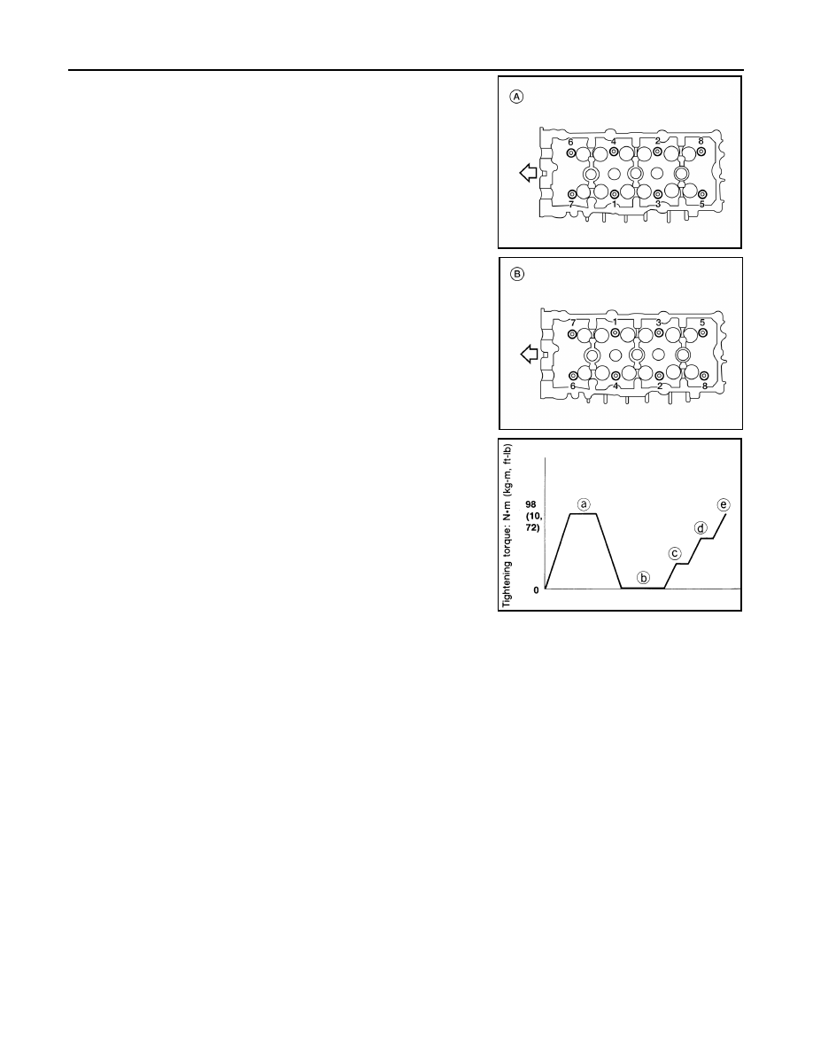
4. Install the cylinder heads RH (A) and LH (B) on the cylinder

block. Tighten the cylinder head bolts in the five steps in the

numerical order as shown using Tool.

• Tightening procedure:

5. Installation of the remaining components is in the reverse order of removal.

Tool Number

: KV10112100 (BT-8653-A)

AWBIA1412ZZ

AWBIA1413ZZ

Cylinder head bolts
Step a

: 98.1 N·m (10 kg-m, 72 ft-lb)

Step b

: Loosen in the reverse order of tightening

Step c  : 39.2 N·m (4.0 kg-m, 29 ft-lb)
Step d

: 103

° degrees rotation clockwise

Step e

: 103

° degrees rotation clockwise

SEM879EA

CYLINDER HEAD

EM-93

< REMOVAL AND INSTALLATION >

C

D

E

F

G

H

I

J

K

L

M

A

EM

N

P

O

Disassembly and Assembly

INFOID:0000000009466047

CAUTION:

• When installing camshafts, chain tensioners, oil seals, or other sliding parts, lubricate contacting

surfaces with new engine oil.

• Apply new engine oil to threads and seat surface when installing cylinder head, camshaft sprocket,

crankshaft pulley, and camshaft bracket.

AWBIA1353ZZ

1.

Valve collet

2.

Valve spring retainer

3.

Valve spring

4.

Valve oil seal

5.

Valve spring seat

6.

Valve guide

7.

Spark plug tube

8.

Lifter (INT)

9.

Lifter (EXH)

10. Cylinder head

11. Valve seat (EXH)

12. Valve seat (INT)

13. Valve (EXH)

14. Valve (INT)

EM-94

< REMOVAL AND INSTALLATION >

CYLINDER HEAD

• Attach tags to valve lifters so as not to mix them up.

DISASSEMBLY

1. Remove spark plug.
2. Remove valve lifter.

• Identify installation positions, and store them without mixing them up.

3. Remove valve collet.

• Compress valve spring and remove valve collet with magnet

hand using Tool.

CAUTION:

When working, take care not to damage valve lifter holes.

4. Remove valve spring retainer, valve spring and valve spring seat.
5. Push valve stem to combustion chamber side, and remove valve.

• Identify installation positions, and store them without mixing them up.

6. Remove valve oil seals using Tool.

7. If valve seat must be replaced, refer to 

EM-95, "Inspection After Disassembly"

.

8. If valve guide must be replaced, refer to 

EM-95, "Inspection After Disassembly"

.

9. Remove spark plug tube, as necessary.

• Using pair of pliers, pull spark plug tube out of cylinder head. 

CAUTION:

• Take care not to damage cylinder head.

• Once removed, spark plug tube will be deformed and cannot be reused. Do not remove it unless

absolutely necessary.

ASSEMBLY

1. When valve guide is removed, install it. Refer to 

EM-95, "Inspection After Disassembly"

.

2. When valve seat is removed, install it. Refer to 

EM-95, "Inspection After Disassembly"

.

3. Install valve oil seals using Tool.

4. Install valve spring seat.
5. Install valves.

• Install it in the original position.

NOTE:

Larger diameter valves are for intake side.

Tool numbers

: KV10109220 (

)

: KV10116200 (J-26336-A)
: KV10115900 (J-26336-20)

WBIA0578E

Tool number

: KV10107902 (J-38959)

WBIA0489E

Tool number

:

 (J-39386)

Height "H" (Without valve spring seat installed)

Intake and exhaust

: 14.3 - 14.9 mm (0.563 - 0.587 in)

WBIA0490E

CYLINDER HEAD

EM-95

< REMOVAL AND INSTALLATION >

C

D

E

F

G

H

I

J

K

L

M

A

EM

N

P

O

6. Install valve spring (uneven pitch type) with narrow pitch end

(paint mark) to cylinder head side (valve spring seat side).

7. Install valve spring retainer.
8. Install valve collet.

• Compress valve spring with valve spring compressor, attach-

ment and adapter using Tool. Install valve collet with magnet

hand.

CAUTION:

When working, take care not to damage valve lifter holes.

• Tap valve stem edge lightly with plastic hammer after installa-

tion to check its installed condition.

9. Install valve lifter.

• Install valve lifter in the original position.

10. Install spark plug tube.

• Press-fit spark plug tube as follows:

a. Remove old liquid gasket adhering to cylinder head mounting hole.
b. Apply sealant to area within approximately 12 mm (0.47 in) from edge of spark plug tube press-fit side.

Use Genuine High Strength Locking Sealant or equivalent. Refer to 

GI-21, "Recommended Chemi-

cal Products and Sealants"

.

c. Press-fit spark plug tube so that its height “H” is as specified in

using suitable tool.

CAUTION:

• When press-fitting, take care not to deform spark plug

tube.

• After press-fitting, wipe off liquid gasket protruding onto

cylinder-head upper face.

11. Install spark plug. Refer to 

EM-12, "Removal and Installation"

.

Inspection After Disassembly

INFOID:0000000009466048

CYLINDER HEAD DISTORTION

Clean the surface of the cylinder head. Use a reliable straightedge and feeler gauge to check the flatness of

cylinder head surface.

SEM085D

Tool numbers

: KV10109220 (

)

: KV10116200 (J-26336-A)
: KV10115900 (J-26336-20)

WBIA0578E

Press-fit height “H” : 37.7 - 38.7 mm (1.484 - 1.529 in)

PBIC2638E


Content   ..  549  550  551  552   ..