Nissan Maxima. Manual - part 550


  Index      Nissan     Nissan Maxima (2009-2014 year) - Service and Repair Manual


Search            


Content   ..  548  549  550  551   ..


Nissan Maxima. Manual - part 550


EM-88

< REMOVAL AND INSTALLATION >

OIL SEAL

2. Install crankshaft pulley and tighten the bolt in two steps.

• Lubricate thread and seat surface of the bolt with new engine oil.

• For the second step angle tighten using Tool.

3. Remove the Tool to unlock the drive plate. 

CAUTION:

Do not damage the ring gear teeth, or the signal plate teeth behind the ring gear, when removing

the Tool.

4. Installation of the remaining components is in reverse order of removal. 

Removal and Installation of Rear Oil Seal

INFOID:0000000009466045

REMOVAL

1. Remove the upper oil pan. Refer to 

EM-37, "Removal and Installation (Upper Oil Pan)"

.

2. Remove drive plate. Refer to 

EM-127, "Dowel Pin Alignment"

.

3. Remove rear oil seal retainer using Tool.

CAUTION:

• Be careful not to damage mating surface.

• If rear oil retainer is removed, replace it with a new one

NOTE:

Rear oil seal and retainer form a single part and are replaced as

an assembly.

INSTALLATION

1. Remove old liquid gasket material from mating surface of cylinder block and oil pan using a suitable

scraper.

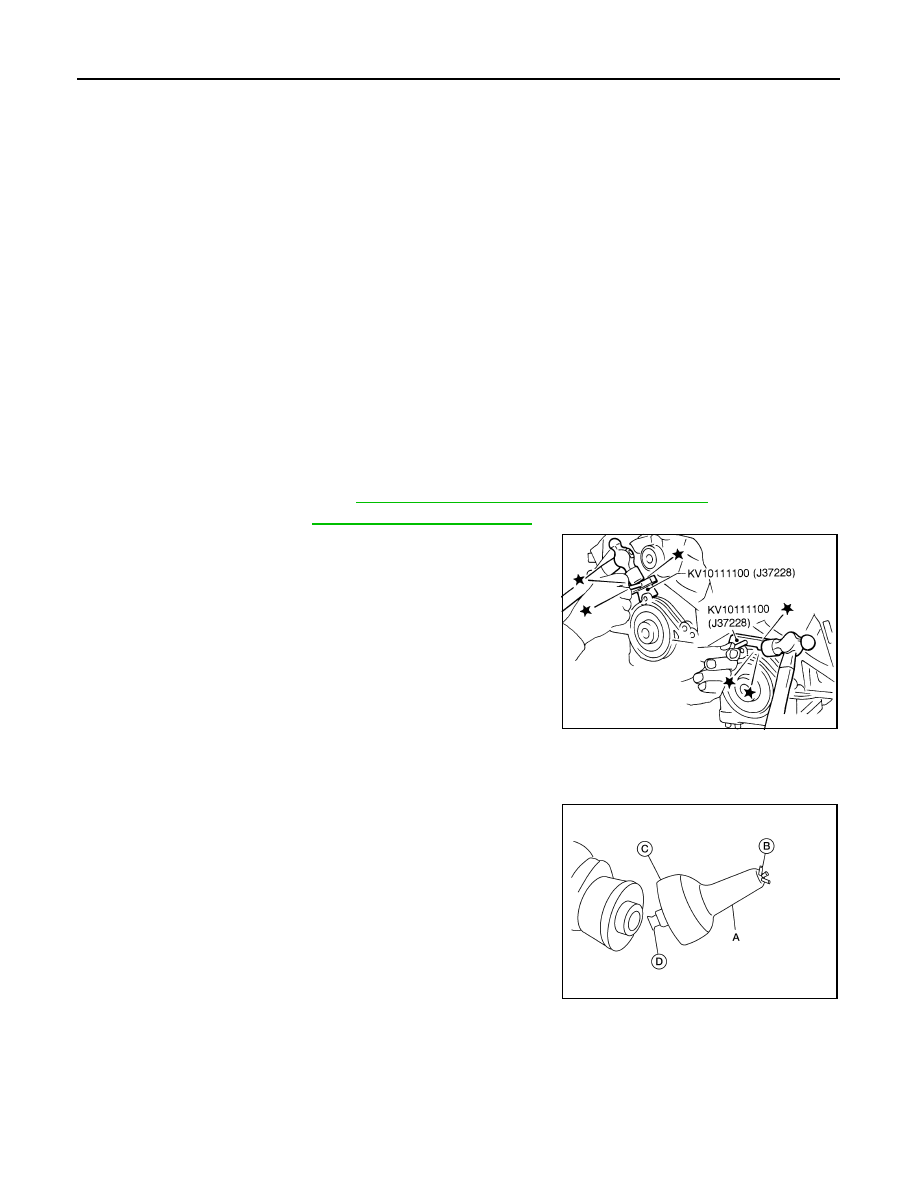
2. Install the rear oil seal retainer using Tool (A).

a. Loosen the wing nut (B) on the end of the Tool (A).
b. Insert the arbor (D) into the crankshaft pilot hole until the outer

lip (C) of the Tool (A) covers the edge of the crankshaft sealing

surface.

c.

Tighten the wing nut (B) to secure the Tool (A) to the crankshaft.

Step 1

: 44.1 N·m (4.5 kg-m, 33 ft-lb)

Step 2 

: 84

° - 90° degrees clockwise

Tool number

: KV10112100 (BT-8653-A)

Tool number

: — (J-50288)

Tool Number

: KV10111100 (J-37228)

SEM830E

Tool number

:   —   (J-47128)

ALBIA0652ZZ

OIL SEAL

EM-89

< REMOVAL AND INSTALLATION >

C

D

E

F

G

H

I

J

K

L

M

A

EM

N

P

O

d. Apply sealant to rear oil seal retainer as shown.

Use Genuine Silicone RTV Sealant, or equivalent. Refer to

GI-21, "Recommended Chemical Products and Sealants"

.

CAUTION:

• Installation should be done within 5 minutes after apply-

ing liquid gasket.

• Do not fill the engine with oil for at least 30 minutes after

the components are installed to allow the sealant to cure.

e. Lubricate the sealing surface of the new rear main seal with new engine oil.
f.

Slide the new rear main seal (1) over the Tool (A) and onto the

crankshaft.

g. Loosen the wing nut and push the threaded rod into the handle

to remove the Tool (A).

h. Tighten the rear oil seal retainer bolts to specification.

3. Installation of the remaining components is in the reverse order of removal.

CAUTION:

• When replacing an engine or transmission you must make sure the dowels are installed cor-

rectly during re-assembly.

• Improper alignment caused by missing dowels may cause vibration, oil leaks or drivetrain com-

ponent damage.

AWBIA0028ZZ

ALBIA0653ZZ

EM-90

< REMOVAL AND INSTALLATION >

CYLINDER HEAD

CYLINDER HEAD

Removal and Installation

INFOID:0000000009466046

REMOVAL

CAUTION:

Do not rotate crankshaft and camshaft separately or valves will strike piston heads.
1. Remove the engine and transaxle assembly. Refer to 

EM-103, "Removal and Installation"

.

2. Remove the rear timing chain case. Refer to 

EM-71, "Removal and Installation"

.

3. Remove the intake manifold. Refer to 

EM-28, "Removal and Installation"

.

4. Remove the intake and exhaust camshafts. Refer to 

EM-76, "Removal and Installation"

.

5. Remove the coolant outlet housing. Refer to 

CO-24, "Removal and Installation"

.

6. Remove the RH (A) and LH (B) cylinder head bolts, with power

tool.

• The bolts should be loosened gradually in three stages.

• Loosen the bolts in the numerical order as shown.

ALBIA0260ZZ

1.

Cylinder head bolt

2.

Cylinder head

3.

Cylinder head gasket

4.

Engine block

A.

Refer to INSTALLATION

AWBIA1412ZZ

AWBIA1413ZZ

CYLINDER HEAD

EM-91

< REMOVAL AND INSTALLATION >

C

D

E

F

G

H

I

J

K

L

M

A

EM

N

P

O

7. Remove cylinder heads and gaskets.

• Discard the cylinder head gaskets and use new gaskets for

installation.

INSTALLATION

1. Turn the crankshaft until No. 1 piston is set at TDC on the com-

pression stroke.

• The crankshaft key should line up with the right bank cylinder

center line as shown.

2. Install new gaskets on the cylinder heads.

CAUTION:

Do not reuse cylinder head gasket.

3. Inspect the cylinder head bolts before installing the cylinder heads.

CAUTION:

Cylinder head bolts are tightened by degree rotation tight-

ening method. Whenever the size difference between d1

and d2 exceeds the limit, replace the bolts with new ones.

• Lubricate threads and seat surfaces of the bolts with new

engine oil.

SEM863E

SEM532G

SEM445G

Limit (d1 - d2)

: 0.11 mm (0.0043 in)

SEM957E


Content   ..  548  549  550  551   ..