Nissan Maxima. Manual - part 549


  Index      Nissan     Nissan Maxima (2009-2014 year) - Service and Repair Manual


Search            


Content   ..  547  548  549  550   ..


Nissan Maxima. Manual - part 549


EM-84

< REMOVAL AND INSTALLATION >

CAMSHAFT

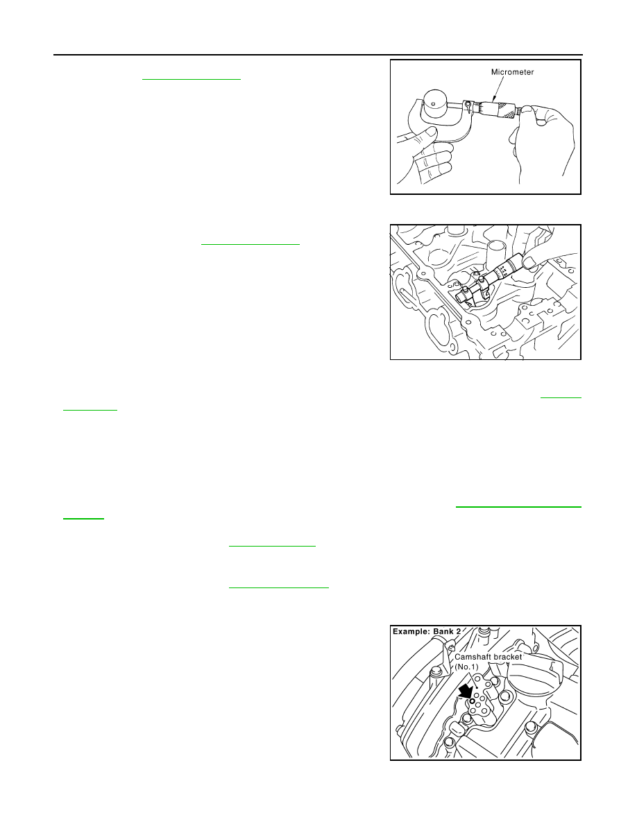
• Measure the outer diameter of the valve lifter using suitable tool as

shown. Refer to 

EM-130, "Camshaft"

.

• If out of the specified range, replace the valve lifter.

Valve Lifter Bore Diameter

• Measure diameter of valve lifter bore of cylinder head using suit-

able tool as shown. Refer to 

EM-130, "Camshaft"

.

• If out of the specified range, replace the cylinder head assembly.

Calculation of Valve Lifter Clearance

• (Valve lifter clearance) = (hole diameter for valve lifter) – (outer diameter of valve lifter) Refer to 

EM-130,

"Camshaft"

.

• If out of specified range, replace either or both valve lifter and cylinder head assembly.

Inspection after Installation

INFOID:0000000009466042

INSPECTION OF CAMSHAFT SPROCKET (INT) OIL GROOVE

CAUTION:

• Perform this inspection only when DTC P0011 is detected in self-diagnostic results of CONSULT III

and it is directed according to inspection procedure of EC section. Refer to 

EC-177, "Diagnosis Pro-

cedure"

.

• Check when engine is cold so as to prevent burns from any splashing engine oil.
1. Check engine oil level. Refer to 

LU-8, "Inspection"

.

2. Perform the following procedure so as to prevent the engine from being unintentionally started while

checking.

a. Release fuel pressure. Refer to 

EC-592, "Inspection"

.

b. Disconnect ignition coil and injector harness connectors if practical.
3. Remove intake valve timing control solenoid valve.
4. Crank engine, and then make sure that engine oil comes out

from intake valve timing control solenoid valve cover oil hole.

End cranking after checking.

WARNING:

Be careful not to touch rotating parts (drive belts, idler pul-

ley, and crankshaft pulley, etc.).

CAUTION:

• Engine oil may squirt from intake valve timing control

solenoid valve installation hole during cranking. Use a

shop cloth to prevent engine oil from splashing on

worker, engine components and vehicle. 

• Do not allow engine oil to get on rubber components such

as drive belts or engine mount insulators. Immediately wipe off any splashed engine oil.

JEM798G

SEM867E

KBIA2686E

CAMSHAFT

EM-85

< REMOVAL AND INSTALLATION >

C

D

E

F

G

H

I

J

K

L

M

A

EM

N

P

O

5. Clean oil groove between oil strainer and intake valve timing control solenoid valve if engine oil does not

come out from intake valve timing control solenoid valve cover oil hole. 

6. Remove components between intake valve timing control solenoid valve and camshaft sprocket (INT),

and then check each oil groove for clogging.

• Clean oil groove if necessary. 

7. After inspection, installation of the remaining components is in the reverse order of removal.

EM-86

< REMOVAL AND INSTALLATION >

OIL SEAL

OIL SEAL

Removal and Installation of Valve Oil Seal

INFOID:0000000009466043

REMOVAL

1. Turn crankshaft until the cylinder requiring new oil seals is at TDC. This will prevent valve from dropping

into cylinder.

CAUTION:

When rotating crankshaft, be careful to avoid scarring the front cover with the timing chain.

2. Remove camshaft relating to valve oil seal to be removed. Refer to 

EM-76, "Removal and Installation"

.

3. Remove valve lifters. Refer to 

EM-76, "Removal and Installation"

.

4. Remove valve collet, valve spring retainer and valve spring

using Tool.

CAUTION:

When working, take care not to damage valve lifter holes.

• Compress valve spring using Tool attachment, adapter.

Remove valve collet with magnet hand.

5. Remove valve oil seal using Tool.

INSTALLATION

1. Apply new engine oil to new valve oil seal joint surface and seal lip.
2. Press in valve oil seal to height (H) using Tool to specified

height.

NOTE:

Dimension (H): height measured before valve spring seat instal-

lation.

3. Installation of the remaining components is in the reverse order

of removal.

Removal and Installation of Front Oil Seal

INFOID:0000000009466044

REMOVAL

1. Remove engine under cover. Refer to 

EXT-15, "Exploded View"

.

2. Remove drive belt. Refer to 

EM-14, "Removal and Installation"

.

3. Remove radiator fan. Refer to 

CO-16, "Removal and Installation"

.

Tool numbers

: KV10116200 (J-26336-A)
: KV10115900 (J-26336-20)
: KV10109220 ( — )

WBIA0578E

Tool number

: KV10107902 (J-38959)

WBIA0489E

Tool number

(J-39386)

Intake and exhaust

: 14.3 - 14.9 mm (0.563 - 0.587 in)

WBIA0490E

OIL SEAL

EM-87

< REMOVAL AND INSTALLATION >

C

D

E

F

G

H

I

J

K

L

M

A

EM

N

P

O

4. Remove rear cover plate.
5. Remove the crankshaft pulley as follows: 
a. Lock the drive plate using Tool.

CAUTION:

Do not damage the ring gear teeth, or the signal plate teeth behind the ring gear, when setting the

Tool.

b. Loosen crankshaft pulley and locate bolt seating surface at 10 mm (0.39 in) from its original position.
c. Position a pulley puller at recess hole of crankshaft pulley to

remove crankshaft pulley.

CAUTION:

Do not use a puller claw on the outer diameter of the crank-

shaft pulley.

6. Remove front oil seal from front cover using a suitable tool.

CAUTION:

Be careful not to damage front cover or crankshaft.

INSTALLATION

1. Apply new engine oil to new oil seal and install.

• Install new oil seal in the direction as shown.

CAUTION:

Press fit straight and avoid causing burrs or tilting the oil

seal.

• Press-fit oil seal until it becomes flush with the timing chain case

end face, using suitable tool.

• Make sure the garter spring in the oil seal is in position and seal lip

is not inverted.

Tool number

:  — (J-50288)

EMQ0477D

WBIA0680E

SEM715A

PBIC0790E


Content   ..  547  548  549  550   ..