Nissan Maxima. Manual - part 547
EM-76
< REMOVAL AND INSTALLATION >
CAMSHAFT
CAMSHAFT
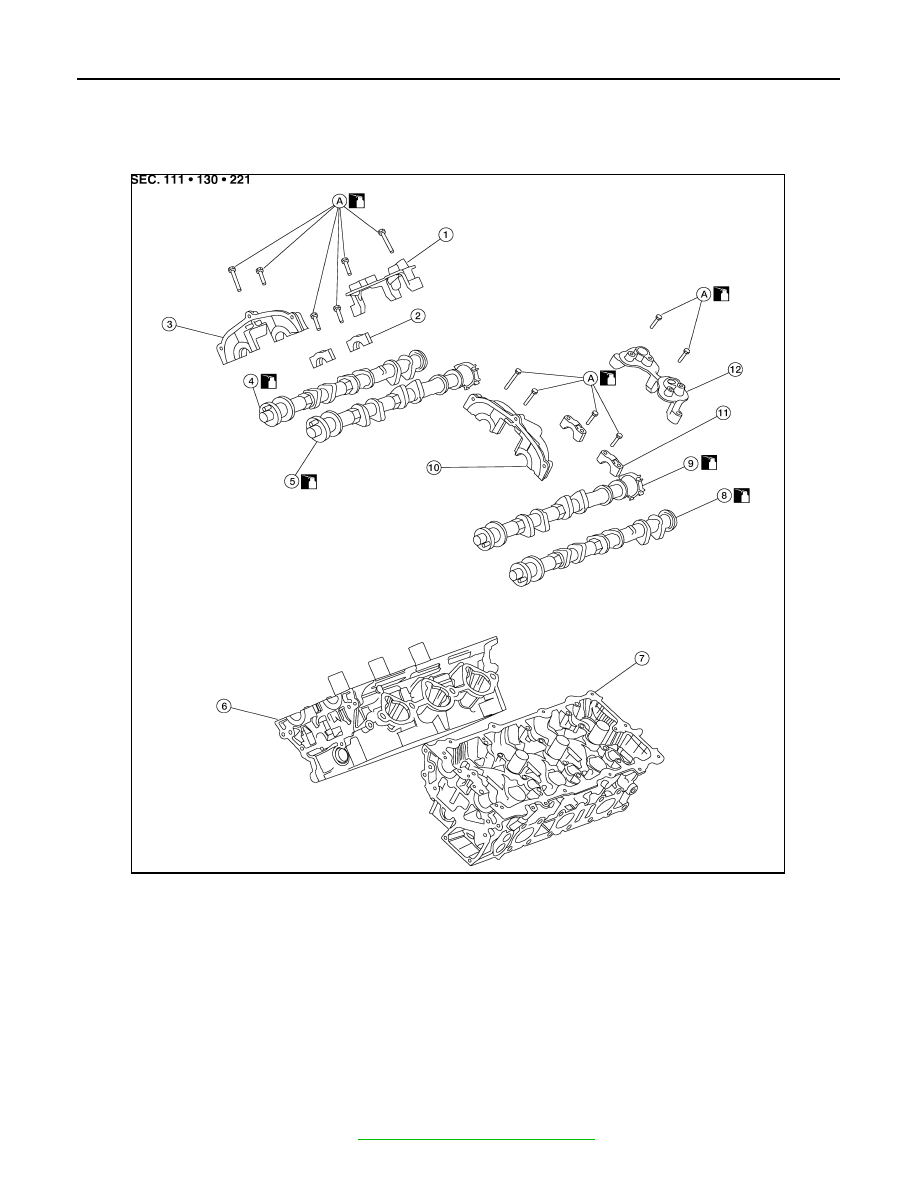
Exploded View
INFOID:0000000009466039
CAUTION:
Apply new engine oil to parts marked in illustration before installation.
Removal and Installation
INFOID:0000000009466040
REMOVAL
1. Remove the timing chains. Refer to
EM-64, "Removal and Installation"
.
1.
Camshaft position sensor bracket
(RH)
2.
Camshaft brackets
3.
No. 1 camshaft bracket (RH)
4.
Camshaft (EXH) (RH)
5.
Camshaft (INT) (RH)
6.
Cylinder head (RH)
7.
Cylinder head (LH)
8.
Camshaft (EXH) (LH)
9.
Camshaft (INT) (LH)
10. No. 1 camshaft bracket (LH)
11. Camshaft brackets
12. Camshaft position sensor bracket (LH)
A.
Refer to INSTALLATION
AWBIA1178GB