Nissan Maxima. Manual - part 545


  Index      Nissan     Nissan Maxima (2009-2014 year) - Service and Repair Manual


Search            


Content   ..  543  544  545  546   ..


Nissan Maxima. Manual - part 545


EM-68

< REMOVAL AND INSTALLATION >

TIMING CHAIN

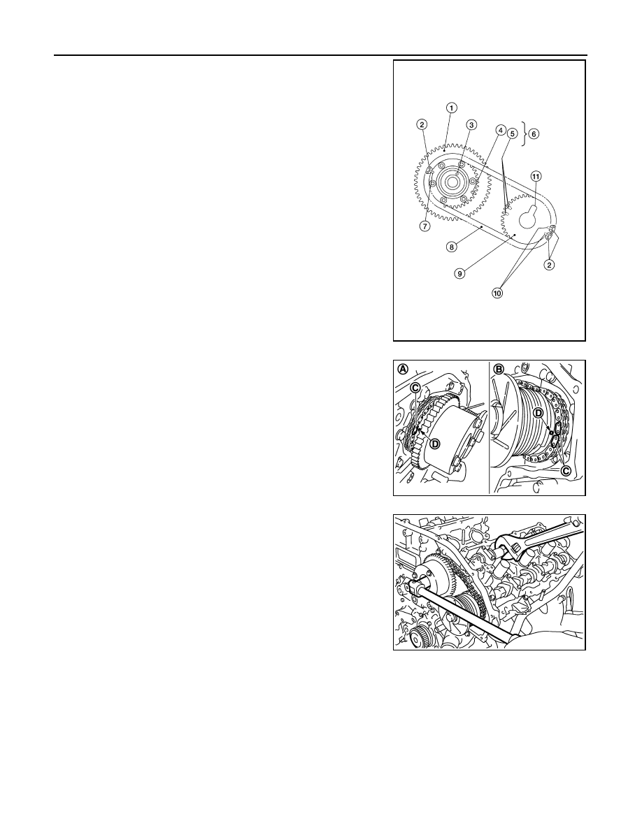
a. Align the matching marks (4), (5), (7) and (10) on the timing

chain (secondary) (8) (orange link) (2) with the ones on the cam-

shaft sprockets (INT) and (EXH) (punched), and install them.

• Matching marks for the camshaft sprocket (INT) are on the

back side of the secondary sprocket.

• There are two types of matching marks:

- RH bank use round type (7) and (10).

- LH bank (6): use oval type (4) and (5).

b. Align the dowel pin with the pin hole (3) on the camshaft

sprocket (INT) side (1), and dowel pin groove (11) with the dowel

pin on the camshaft sprocket (EXH) side (9), and install them.

• Camshaft sprocket bolts must be tightened in the next step.

Tightening them by hand is enough to prevent the dislocation

of the dowel pins (3) and dowel pin grooves (11).

• Check mating mark (punched) (D) on each camshaft sprocket

is positioned on the mating marks (orange link) (C) on timing

chain (secondary).

NOTE:

Ensure the mating mark (punched) (D) on the camshaft sprocket

is aligned with the mating marks (orange link) (C) on the timing

chain (secondary).

4. After confirming the mating marks are aligned, tighten the cam-

shaft sprocket bolts.

• Secure the camshaft using a wrench at the hexagonal portion

to tighten the bolts.

WBIA0689E

(A) : Intake side
(B) : Exhaust side

JPBIA0114ZZ

KBIA4379J

TIMING CHAIN

EM-69

< REMOVAL AND INSTALLATION >

C

D

E

F

G

H

I

J

K

L

M

A

EM

N

P

O

5. Pull the stopper pins (2) out from the timing chain tensioners

(secondary) (1).

6. Install the crankshaft sprocket on the crankshaft.

• Make sure the mating marks on the crankshaft sprocket face

the front of the engine.

7. Install the timing chain (primary).

• Install timing chain (primary) so the mating mark punched (B)

on camshaft sprocket (C) is aligned with the pink link (A) on

the timing chain, while the mating mark (notched) (E) on the

crankshaft sprocket (D) is aligned with the orange one (F) on

the timing chain, as shown.

• When it is difficult to align mating marks of the timing chain

(primary) with each sprocket, gradually turn the camshaft

using a wrench on the hexagonal portion to align it with the

mating marks.

• During alignment, be careful to prevent dislocation of mating

mark alignments of the secondary timing chains.

(G): Water pump

(A) : Bank 1
(B) : Bank 2

JPBIA0087ZZ

SEM929E

WBIA0721E

EM-70

< REMOVAL AND INSTALLATION >

TIMING CHAIN

8. Install the internal chain guide (1), slack guide (2) and timing

chain (primary).

CAUTION:

Do not overtighten the slack guide bolts. It is normal for a

gap to exist under the bolt seats when the bolts are tight-

ened to specification.

9. Install the timing chain tensioner (primary) for the slack guide.

• When installing the timing chain tensioner (primary), push in

the sleeve and keep it pressed in with the stopper pin.

• Remove any dirt and foreign materials completely from the

back and the mounting surfaces of the timing chain tensioner

(primary).

• After installation, pull out the stopper pin while pressing the

slack guide.

10. Reconfirm that the matching marks on the sprockets and the

timing chain have not slipped out of alignment.

11. Install the front timing chain case. Refer to 

EM-54, "Removal and Installation"

.

JPBIA0086ZZ

SEM741G

SEM733G

REAR TIMING CHAIN CASE

EM-71

< REMOVAL AND INSTALLATION >

C

D

E

F

G

H

I

J

K

L

M

A

EM

N

P

O

REAR TIMING CHAIN CASE

Exploded View

INFOID:0000000009466037

Removal and Installation

INFOID:0000000009466038

CAUTION:

• After removing timing chain, do not turn the crankshaft and camshaft separately, or the valves will

strike the pistons.

• Before removing the upper oil pan, remove the crankshaft position sensor (POS).

• Be careful not to damage sensor edges.

• Do not reuse O-ring.

REMOVAL

1. Remove the engine assembly. Refer to 

EM-103, "Removal and Installation"

.

2. Remove the oil pan lower and upper. Refer to 

EM-37, "Removal and Installation (Upper Oil Pan)"

.

3. Remove the front timing chain case. Refer to 

EM-54, "Exploded View"

.

4. Remove the timing chains (primary) and (secondary). Refer to 

EM-64, "Removal and Installation"

.

5. Remove No. 1 camshaft bracket (RH) and No. 1 camshaft bracket (LH). Refer to 

EM-76, "Removal and

Installation"

.

1.

Rear timing chain case

2.

O-ring

3.

Cylinder block

AWBIA0852GB


Content   ..  543  544  545  546   ..