Nissan Maxima. Manual - part 510
EC-524
< ECU DIAGNOSIS INFORMATION >
[VQ35DE]
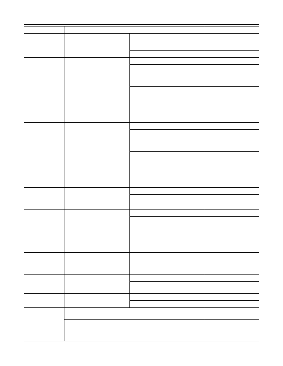
ECM
PURG VOL C/V
• Engine: After warming up
• Selector lever: P or N
• Air conditioner switch: OFF
• No load
Idle
(Accelerator pedal: Not depressed even
slightly, after engine starting.)
0%
2,000 rpm
—
INT/V TIM (B1)
• Engine: After warming up
• Selector lever: P or N
• Air conditioner switch: OFF
• No load
Idle
−5° - 5°CA
2,000 rpm
Approx. 0
° - 30°CA
INT/V TIM (B2)
• Engine: After warming up
• Selector lever: P or N
• Air conditioner switch: OFF
• No load
Idle
−5° - 5°CA
2,000 rpm
Approx. 0
° - 30°CA
EXH/V TIM (B1)
• Engine: After warming up
• Selector lever: P or N
• Air conditioner switch: OFF
• No load
Idle
−5° - 5°CA
Around 2,500 rpm while the engine speed
is rising
Approx. 0
° - 30°CA
EXH/V TIM (B2)
• Engine: After warming up
• Selector lever: P or N
• Air conditioner switch: OFF
• No load
Idle
−5° - 5°CA
Around 2,500 rpm while the engine speed
is rising
Approx. 0
° - 30°CA
INT/V SOL (B1)
• Engine: After warming up
• Selector lever: P or N
• Air conditioner switch: OFF
• No load
Idle
0% - 2%
2,000 rpm
Approx. 0% - 50%
INT/V SOL (B2)
• Engine: After warming up
• Selector lever: P or N
• Air conditioner switch: OFF
• No load
Idle
0% - 2%
2,000 rpm
Approx. 0% - 50%
VTC DTY EX B1
• Engine: After warming up
• Selector lever: P or N
• Air conditioner switch: OFF
• No load
Idle
0% - 2%
Around 2,500 rpm while the engine speed
is rising
Approx. 0% - 70%
VTC DTY EX B2
• Engine: After warming up
• Selector lever: P or N
• Air conditioner switch: OFF
• No load
Idle
0% - 2%
Around 2,500 rpm while the engine speed
is rising
Approx. 0% - 70%
VIAS S/V-1
• Engine: After warming up
• Selector lever: P or N
• Air conditioner switch: OFF
• No load
When revving engine up to 5,000 rpm
quickly
OFF
→ON → OFF
VIAS S/V-2
• Engine: After warming up
• Selector lever: P or N
• Air conditioner switch: OFF
• No load
When revving engine up to 5,000 rpm
quickly
OFF
→ON → OFF
AIR COND RLY
• Engine: After warming up, idle the
engine
Air conditioner switch: OFF
OFF
Air conditioner switch: ON
(Compressor operates)
ON
ENGINE MOUNT
• Engine: After warming up
Below 950 rpm
IDLE
Above 950 rpm
TRVL
FUEL PUMP RLY
• For 1 second after turning ignition switch: ON
• Engine running or cranking
ON
• Except above
OFF
VENT CONT/V
• Ignition switch: ON
OFF
THRTL RELAY
• Ignition switch: ON
ON
Monitor Item
Condition
Values/Status