Nissan Maxima. Manual - part 508


  Index      Nissan     Nissan Maxima (2009-2014 year) - Service and Repair Manual


Search            


Content   ..  506  507  508  509   ..


Nissan Maxima. Manual - part 508


EC-516

< DTC/CIRCUIT DIAGNOSIS >

[VQ35DE]

REFRIGERANT PRESSURE SENSOR

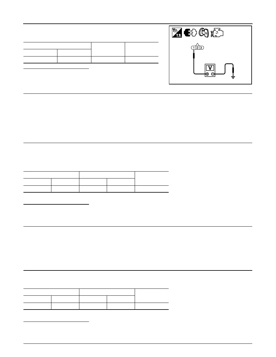
3. Check the voltage between refrigerant pressure sensor harness

connector and ground.

Is the inspection result normal?

YES

>> GO TO 4.

NO

>> GO TO 3.

3.

DETECT MALFUNCTIONING PART

Check the following.

• Harness connectors E3, F1

• Junction block connectors E44, E45

• IPDM E/R harness connectors E18, E201

• Harness for open or short between ECM and refrigerant pressure sensor

>> Repair open circuit, short to ground or short to power in harness or connectors.

4.

CHECK REFRIGERANT PRESSURE SENSOR GROUND CIRCUIT FOR OPEN AND SHORT

1. Turn ignition switch OFF.

2. Disconnect ECM harness connector.

3. Check the continuity between refrigerant pressure sensor harness connector and ECM harness connec-

tor.

4. Also check harness for short to ground and short to power.
Is the inspection result normal?

YES

>> GO TO 6.

NO

>> GO TO 5.

5.

DETECT MALFUNCTIONING PART

Check the following.

• Harness connectors E3, F1

• IPDM E/R harness connectors E18, E201

• Harness for open or short between ECM and refrigerant pressure sensor

>> Repair open circuit, short to ground or short to power in harness or connectors.

6.

CHECK REFRIGERANT PRESSURE SENSOR INPUT SIGNAL CIRCUIT FOR OPEN AND SHORT

1. Check the continuity between refrigerant pressure sensor harness connector and ECM harness connec-

tor.

2. Also check harness for short to ground and short to power.
Is the inspection result normal?

YES

>> GO TO 8.

NO

>> GO TO 7.

7.

DETECT MALFUNCTIONING PART

Refrigerant pressure sensor

Ground

Voltage (V)

Connector

Terminal

E219

1

Ground

Approx. 5

JMBIA1619ZZ

Refrigerant pressure sensor

ECM

Continuity

Connector

Terminal

Connector

Terminal

E219

3

F13

40

Existed

Refrigerant pressure sensor

ECM

Continuity

Connector

Terminal

Connector

Terminal

E219

2

F13

39

Existed

REFRIGERANT PRESSURE SENSOR

EC-517

< DTC/CIRCUIT DIAGNOSIS >

[VQ35DE]

C

D

E

F

G

H

I

J

K

L

M

A

EC

N

P

O

Check the following.

• Harness connectors E3, F1

• IPDM E/R harness connectors E18, E201

• Harness for open or short between ECM and refrigerant pressure sensor

>> Repair open circuit, short to ground or short to power in harness or connectors.

8.

CHECK INTERMITTENT INCIDENT

Refer to 

GI-41, "Intermittent Incident"

.

Is the inspection result normal?

YES

>> Replace refrigerant pressure sensor. Refer to 

HAC-105, "Removal and Installation"

 (with color

display) or 

HAC-208, "Removal and Installation"

 (with monochrome display).

NO

>> Repair or replace malfunctioning part. 

EC-518

< DTC/CIRCUIT DIAGNOSIS >

[VQ35DE]

VARIABLE INDUCTION AIR SYSTEM

VARIABLE INDUCTION AIR SYSTEM

Description

INFOID:0000000010095238

Power Valves 1 and 2

The power valves 1 and 2 are installed in intake manifold collector and used to control the suction passage of

the variable induction air control system. They are set in the fully closed or fully opened position by the power

valve actuators 1 and 2 operated by the vacuum stored in the vacuum tank. The vacuum to power valve actu-

ators is controlled by the VIAS control solenoid valves 1 and 2.

Component Function Check

INFOID:0000000010095239

1.

CHECK OVERALL FUNCTION-I

 With CONSULT

1. Start engine and warm it up to the normal operating temperature.

2. Perform “VIAS S/V-1” in “ACTIVE TEST” mode with CONSULT.

3. Turn VIAS control solenoid valve 1 “ON” and “OFF”, and check that power valve actuator 1 rod moves.

 Without CONSULT

1. Start engine and warm it up to the normal operating temperature.

2. When revving engine up to 5,000 rpm quickly.

3. Check that power valve actuator 1 rod moves under the following conditions.

Is the inspection result normal?

1.

Power valve actuator 1

2.

Power valve actuator 1 rod

3.

Power valve actuator 2 rod

4.

Power valve actuator 2
: Vehicle front

1.

Power valve actuator 1

2.

Power valve actuator 1 rod

3.

Power valve actuator 2 rod

4.

Power valve actuator 2
: Vehicle front

Condition

Operation

Idle

Existed

When revving engine up to 5,000 rpm quickly

Not existed

ALBIA0613ZZ

ALBIA0613ZZ

VARIABLE INDUCTION AIR SYSTEM

EC-519

< DTC/CIRCUIT DIAGNOSIS >

[VQ35DE]

C

D

E

F

G

H

I

J

K

L

M

A

EC

N

P

O

YES

>> GO TO 2.

NO

>>

EC-519, "Diagnosis Procedure"

.

2.

CHECK OVERALL FUNCTION-II

 With CONSULT

1. Perform “VIAS S/V-2” in “ACTIVE TEST” mode with CONSULT.

2. Turn VIAS control solenoid valve 2 “ON” and “OFF”, and check that power valve actuator 2 rod moves.

 Without CONSULT

1. When revving engine up to 5,000 rpm quickly.

2. Check that power valve actuator 2 rod moves under the following conditions.

Is the inspection result normal?

YES

>> INSPECTION END

NO

>>

EC-519, "Diagnosis Procedure"

.

Diagnosis Procedure

INFOID:0000000010095240

1.

INSPECTION START

Confirm the malfunctioning system (power valve 1 or power valve 2). Refer to 

EC-518, "Component Function

Check"

.

Which system is related to the incident?

Power valve 1>>GO TO 2.

1.

Power valve actuator 1

2.

Power valve actuator 1 rod

3.

Power valve actuator 2 rod

4.

Power valve actuator 2
: Vehicle front

1.

Power valve actuator 1

2.

Power valve actuator 1 rod

3.

Power valve actuator 2 rod

4.

Power valve actuator 2
: Vehicle front

Condition

Operation

Idle

Existed

When revving engine up to 5,000 rpm quickly

Not existed

ALBIA0613ZZ

ALBIA0613ZZ


Content   ..  506  507  508  509   ..