Nissan Maxima. Manual - part 511
EC-528
< ECU DIAGNOSIS INFORMATION >
[VQ35DE]
ECM
Terminal No.
Description
Condition
Value
(Approx.)
+
-–
Signal name
Input/
Output
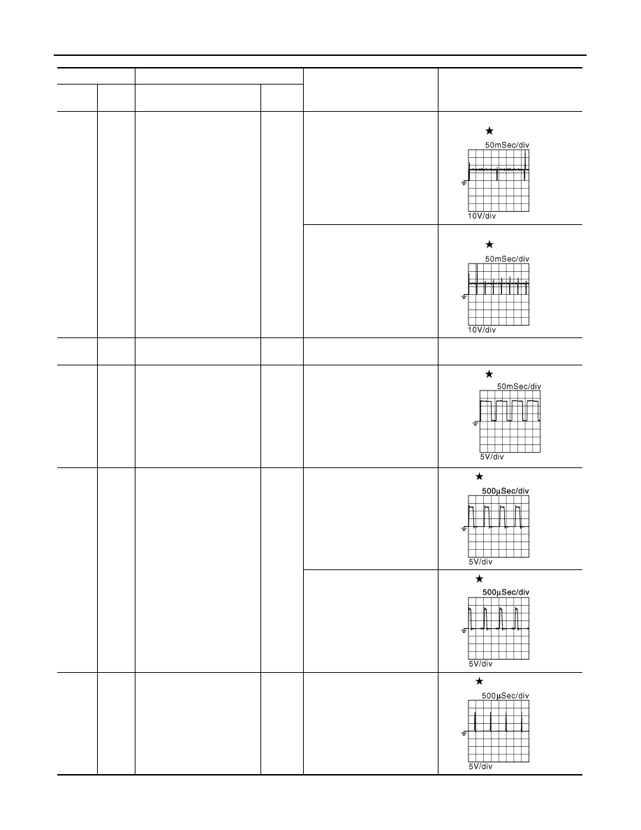
1
(P/B)
112
(B)
Fuel injector No. 6
Output
[Engine is running]
• Warm-up condition
• Idle speed
NOTE:
The pulse cycle changes de-
pending on rpm at idle
BATTERY VOLTAGE
(11 - 14 V)
3
(L/W)
Fuel injector No. 5
29
(LG/R)
Fuel injector No. 4
30
(R/Y)
Fuel injector No. 3
[Engine is running]
• Warm-up condition
• Engine speed: 2,000 rpm
BATTERY VOLTAGE
(11 - 14 V)
31
(R/W)
Fuel injector No. 2
32
(R/B)
Fuel injector No. 1
2
(G/W)
112
(B)
Throttle control motor relay
power supply
Input
[Ignition switch: ON]
BATTERY VOLTAGE
(11 - 14 V)
4
(BR/Y)
112
(B)
A/F sensor 1 heater
(Bank 1)
Output
[Engine is running]
• Warm-up condition
• Idle speed
(More than 140 seconds after
starting engine)
2.9 - 8.8 V
5
(L)
112
(B)
Throttle control motor (Open)
Output
[Ignition switch: ON]
• Engine stopped
• Selector lever: D
• Accelerator pedal: Fully de-
pressed
0 - 14 V
[Ignition switch: ON]
• Engine stopped
• Selector lever: D
• Accelerator pedal: Fully re-
leased
0 - 14 V
6
(P)
112
(B)
Throttle control motor (Close)
Output
[Ignition switch: ON]
• Engine stopped
• Selector lever: D
• Accelerator pedal: Fully re-
leased
0 - 14 V
JMBIA0047GB
JMBIA0048GB
JMBIA0902GB
JMBIA0031GB
JMBIA0032GB
JMBIA1125GB