Nissan Maxima. Manual - part 264
SLIP INDICATOR LAMP
BRC-77
< DTC/CIRCUIT DIAGNOSIS >
[VDC/TCS/ABS]
C
D
E
G
H
I
J
K
L
M
A
B
BRC
N
O
P
SLIP INDICATOR LAMP
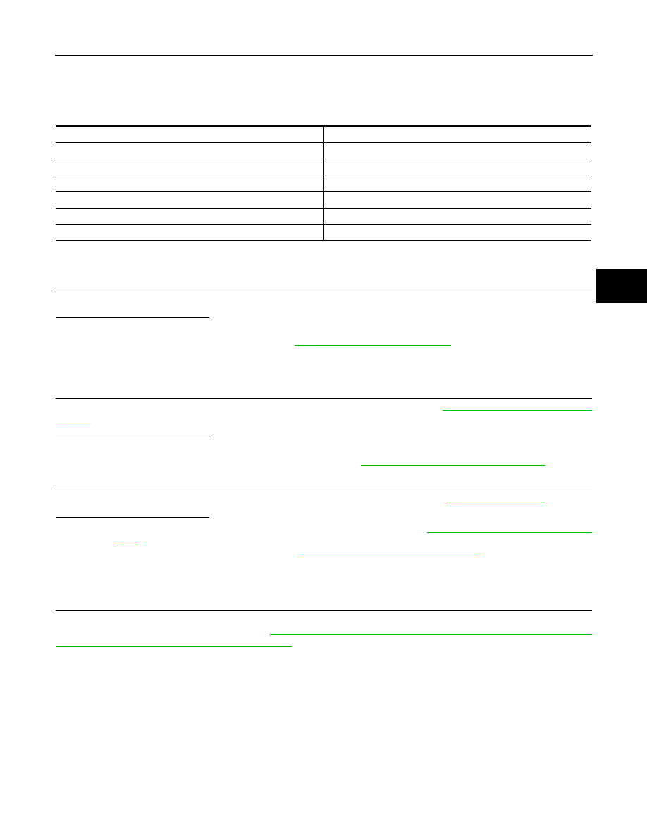
Description
INFOID:0000000010049141
×: ON –: OFF
Component Function Check
INFOID:0000000010049142
1.
CHECK SLIP INDICATOR LAMP OPERATION
Check that the lamp illuminates for approximately 2 seconds after the ignition switch is turned ON.
Is the inspection result normal?
YES
>> Inspection End.
NO
>> Go to diagnosis procedure. Refer to
Diagnosis Procedure
INFOID:0000000010049143
1.
CHECK SELF-DIAGNOSIS
Perform ABS actuator and electric unit (control unit) self-diagnosis. Refer to
Is the inspection result normal?
YES
>> GO TO 2
NO
>> Check items displayed by self-diagnosis. Refer to
BRC-21, "CONSULT Function (ABS)"
2.
CHECK COMBINATION METER
Check if the indication and operation of combination meter are normal. Refer to
.
Is the inspection result normal?
YES
>> Replace ABS actuator and electric unit (control unit). Refer to
BRC-106, "Removal and Installa-
.
NO
>> Replace combination meter. Refer to
MWI-122, "Removal and Installation"
Special Repair Requirement
INFOID:0000000010049144
1.
ADJUSTMENT OF STEERING ANGLE SENSOR NEUTRAL POSITION
Always perform the neutral position adjustment for the steering angle sensor, when replacing the ABS actua-
tor and electric unit (control unit). Refer to
BRC-6, "ADJUSTMENT OF STEERING ANGLE SENSOR NEU-
TRAL POSITION : Special Repair Requirement"
>> END
Condition
SLIP indicator lamp
Ignition switch OFF
–
For 2 seconds after turning ON ignition switch
×
2 seconds later after turning ON ignition switch
–
VDC/TCS function is malfunctioning.
×
ABS function is malfunctioning.
×
EBD function is malfunctioning.
×