Nissan Maxima. Manual - part 223
BCS
COMBINATION SWITCH OUTPUT CIRCUIT
BCS-39
< DTC/CIRCUIT DIAGNOSIS >
[BCM]
C
D
E
F
G
H
I
J
K
L
B
A
O
P
N
COMBINATION SWITCH OUTPUT CIRCUIT
Diagnosis Procedure
INFOID:0000000009467072
Regarding Wiring Diagram information, refer to
.
1.
CHECK OUTPUT 1 - 5 SYSTEM CIRCUIT FOR OPEN
1. Turn the ignition switch OFF.
2. Disconnect the BCM and combination switch.
3. Check continuity between BCM harness connector and combination switch harness connector.
Does continuity exist?
YES
>> GO TO 2
NO
>> Repair or replace harness.
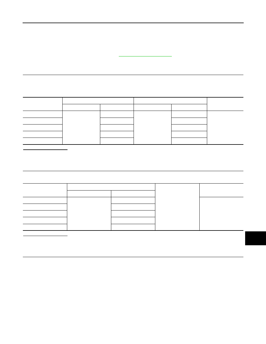
2.
CHECK OUTPUT 1 - 5 SYSTEM CIRCUIT FOR SHORT
Check for continuity between BCM harness connector and ground.
Does continuity exist?
YES
>> Repair or replace harness.
NO
>> GO TO 3
3.
CHECK BCM INPUT VOLTAGE
1. Connect the BCM and the combination switch connector.
2. Check voltage between BCM harness connector and ground.
System
BCM
Combination switch
Continuity
Connector
Terminal
Connector
Terminal
OUTPUT 1
M18 (A)
51
M28 (B)
12
Yes
OUTPUT 2
52
14
OUTPUT 3
53
5
OUTPUT 4
54
2
OUTPUT 5
50
8
System
BCM
Ground
Continuity
Connector
Terminal
OUTPUT 1
M18
51
No
OUTPUT 2
52
OUTPUT 3
53
OUTPUT 4
54
OUTPUT 5
50