Nissan Maxima. Manual - part 189
AV-576
< DTC/CIRCUIT DIAGNOSIS >
[COLOR DISPLAY - W/BOSE & NAVI]
POWER SUPPLY AND GROUND CIRCUIT
3.
CHECK REVERSE POSITION INPUT SIGNAL
1. Connect AV control unit connector.
2. Turn ignition switch ON.
3. Shift transmission into reverse.
4. Check voltage between AV control unit harness connector M163 terminal 53 and ground.
Is voltage reading approximately 12 volts?
YES
>> Replace AV control unit. Refer to
AV-652, "Removal and Installation"
.
NO
>> Check harness for open or short between AV control unit and back-up lamp relay.
4.
CHECK GROUND CIRCUIT
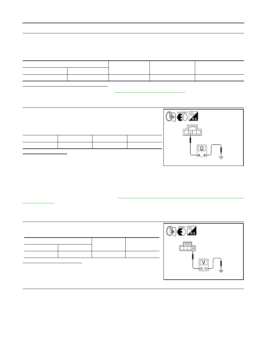
1. Turn ignition switch OFF.
2. Disconnect rear view camera harness connector.
3. Check continuity between rear view camera harness connector
T101 terminal 2 and ground.
Does continuity exist?
YES
>> Inspection End.
NO
>> Repair harness or connector.
MICROPHONE
MICROPHONE : Diagnosis Procedure
INFOID:0000000009471493
Regarding Wiring Diagram information, refer to
AV-614, "Wiring Diagram - With BOSE audio system With Nav-
1.
CHECK POWER SUPPLY CIRCUIT
Check voltage between microphone harness connector R7 terminal
4 and ground.
Is approximately 5V present?
YES
>> GO TO 3.
NO
>> GO TO 2.
2.
CHECK POWER SUPPLY CIRCUIT (CONTINUITY)
(+)
(-)
Transmission position
Value (Approx.)
Connector
Terminal
M163
53
Ground
Reverse
12V
Connector
Terminal
—
Continuity
T101
2
Ground
Yes
AWNIA1725ZZ
(+)
(-)
Value (Approx.)
Connector
Terminal
R7
4
Ground
5V
WKIA5796E