Nissan Maxima. Manual - part 188
AV-572
< DTC/CIRCUIT DIAGNOSIS >
[COLOR DISPLAY - W/BOSE & NAVI]
POWER SUPPLY AND GROUND CIRCUIT
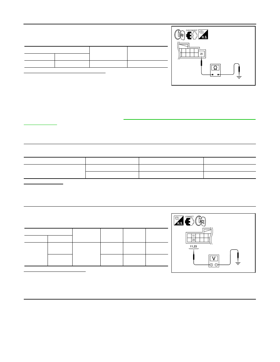
1. Turn ignition switch OFF.
2. Check continuity between AV control unit harness connector
M160 and ground.
Are the continuity results as specified?
YES
>> Inspection End.
NO
>> Repair AV control unit ground.
DISPLAY UNIT
DISPLAY UNIT : Diagnosis Procedure
INFOID:0000000009471489
Regarding Wiring Diagram information, refer to
AV-614, "Wiring Diagram - With BOSE audio system With Nav-
1.
CHECK FUSES
Check that the following display unit fuses are not blown.
Are the fuses OK?
YES
>> GO TO 2.
NO
>> If fuse is blown, be sure to eliminate cause of malfunction before installing new fuse.
2.
CHECK POWER SUPPLY CIRCUIT
1. Turn ignition switch to ACC.
2. Check voltage between display unit harness connector M142
and ground.
Does specified voltage exist?
YES
>> GO TO 3.
NO
>> • Check connector housings for disconnected or loose terminals.
• Repair harness or connector.
3.
CHECK GROUND CIRCUIT
(+)
(-)
Continuity
Connector
Terminal
M160
20
Ground
Yes
AWNIA1930ZZ
Unit
Terminals
Signal name
Fuse No.
Display Unit
11
Battery power
24
23
Ignition switch ACC or ON
17
(+)
(-)
OFF
ACC
ON
Connector
Terminal
M142
11
Ground
Battery
voltage
Battery
voltage
Battery
voltage
23
0V
Battery
voltage
Battery
voltage
ALNIA1217GB