Nissan Maxima. Manual - part 178


  Index      Nissan     Nissan Maxima (2009-2014 year) - Service and Repair Manual


Search            


Content   ..  176  177  178  179   ..


Nissan Maxima. Manual - part 178


AV-532

< SYSTEM DESCRIPTION >

[COLOR DISPLAY - W/BOSE & NAVI]

DIAGNOSIS SYSTEM (AV CONTROL UNIT)

CONTROL UNIT (CAN)

CAN initial diagnosis malfunction is detect-
ed.

Replace the AV control unit if the malfunc-
tion occurs constantly.

CONTROL UNIT (AV)

AV communication circuit initial diagnosis 
malfunction is detected.

FLASH-ROM Error Of Control Unit

AV control unit malfunction is detected.

Connection Of Gyro

Connection of G Sensor

CAN Controller Memory Error

Bluetooth

®

 Module Connection Error

Sub CPU Connection Error

iPod authentification chip error

Audio connection error

DSP Connection Error

AV control unit malfunction is detected.

• If a disc can be played, then there is a 

possibility of the detection of a temporary 
malfunction.

• Replace the AV control unit if the mal-

function occurs constantly.

DSP Communication Error

HDD Connection Error

AV control unit malfunction is detected.

• If the hard disk drive (HDD) is functioning 

normally, there is a possibility of a tempo-
rary malfunction.

• Replace the AV control unit if the mal-

function occurs constantly.

HDD Read Error

HDD Write Error

HDD Communication Error

HDD Access Error

GPS Communication Error

GPS malfunction is detected.

An intermittent error caused by strong radio 
interference may be detected unless any 
symptom (GPS reception error, etc.) oc-
curs.
Replace the AV control unit if the malfunc-
tion occurs constantly.

GPS ROM Error

GPS RAM Error

GPS RTC Error

Unfinished configuration

The writing of configuration data is incom-
plete.

Write configuration data with CONSULT.

USB Controller Communication Error

USB connection malfunction is detected.

Check that the connection to the USB con-
nector is normal.

DVD Mechanism Communication Error

AV control unit malfunction is detected.

• If DVD can be played, then there is a 

possibility of the detection of a temporary 
malfunction.

• Replace the AV control unit if the mal-

function occurs constantly.

Front Display Connection Error

When either one of the following items is 
detected:
• Display unit power supply and ground 

circuits malfunction is detected.

• Malfunction is detected in communica-

tion circuits between AV control unit and 
display unit.

• Malfunction is detected in communica-

tion signal between AV control unit and 
display unit.

• Display unit power supply and ground 

circuits.

• Communication circuits between AV con-

trol unit and display unit.

USB electric current Error

Detection of over current in USB interface.

Check USB harness between the AV con-
trol unit and USB interface. 
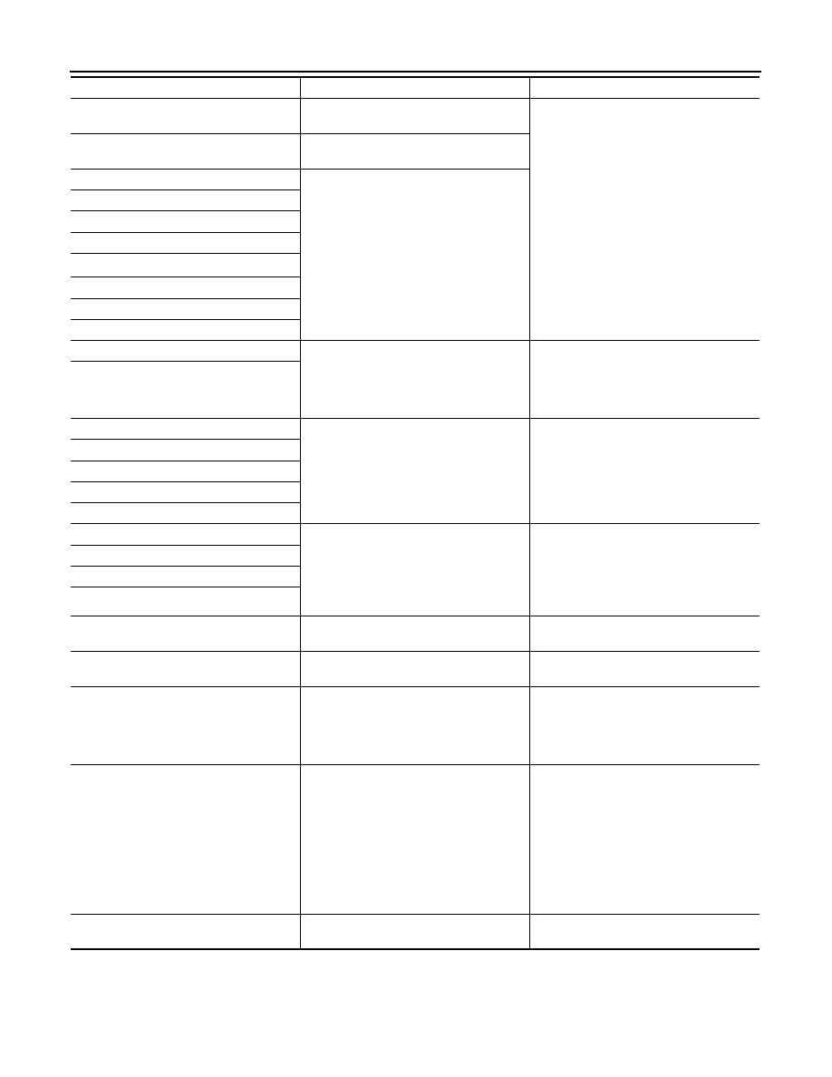
Error item

Description

Possible malfunction factor/Action to take

AV

DIAGNOSIS SYSTEM (AV CONTROL UNIT)

AV-533

< SYSTEM DESCRIPTION >

[COLOR DISPLAY - W/BOSE & NAVI]

C

D

E

F

G

H

I

J

K

L

M

B

A

O

P

Vehicle CAN Diagnosis

• CAN communication status and error counter is displayed.

• The error counter displays “OK” if any malfunction was not

detected in the past and displays “0” if a malfunction is detected. It

increases by 1 if the condition is normal at the next ignition switch

ON cycle. The upper limit of the counter is 39.

• The error counter is erased if “Reset” is pressed.

NOTE:

“???” indicates UNKWN

AV COMM Diagnosis

• Displays the communication status between AV control unit (mas-

ter unit) and each unit.

• The error counter displays “OK” if any malfunction was not

detected in the past and displays “0” if a malfunction is detected. It

increases by 1 if the condition is normal at the next ignition switch

ON cycle. The upper limit of the counter is 39.

• The error counter is erased if “Reset” is pressed.

NOTE:

“???” indicates UNKWN

Hands-Free Phone

GPS Antenna Error

GPS antenna connection malfunction is de-
tected.

Check the connection of the GPS antenna 
connector.

• AV COMM CIRCUIT
• Switches Connection Error

When either one of the following items are 
detected:
• Multifunction switch power supply and 

ground circuits are malfunctioning.

• AV communication circuits between AV 

control unit and multifunction switch are 
malfunctioning.

• Multifunction switch power supply and 

ground circuits.

• AV communication circuits between AV 

control unit and multifunction switch.

Error item

Description

Possible malfunction factor/Action to take

Items

Display (Current)

Malfunction counter

(Past)

Tx(HVAC)

OK / ???

OK / 0 – 39

Rx(ECM)

OK / ???

OK / 0 – 39

Rx(Cluster)

OK / ???

OK / 0 – 39

Rx(HVAC)

OK / ???

OK / 0 – 39

Rx(USM)

OK / ???

OK / 0 – 39

Rx(STRG)

OK / ???

OK / 0 – 39

JSNIA2181ZZ

Items

Status

(Current)

Counter

(Past)

C Tx(ITM–PrimarySW)

OK / ???

OK / 0 – 39

C Rx(PrimarySW–ITM)

OK / ???

OK / 0 – 39

NNNIA0189ZZ

AV-534

< SYSTEM DESCRIPTION >

[COLOR DISPLAY - W/BOSE & NAVI]

DIAGNOSIS SYSTEM (AV CONTROL UNIT)

The hands-free phone reception volume adjustment and microphone

and speaker test functions are also available.

Camera

The four functions of “Correct Draw Line of Rear View Camera”,

“Alter/Confirm Configuration”, “Reset Configuration” and “Camera

Syst Type” are available.

Correct Draw Line of Rear View Camera

• Use this mode to adjust the guide line display position of the rear-

view monitor if necessary after removing the rear view monitor

camera.

Alter/Confirm Configuration

• Configuration stored in the AV control unit can be checked and modified.

Configuration list

JSNIA2183ZZ

AWNIA1925GB

JSNIA0085GB

Setting item

Setting

Setting item

Setting

Predi. Course Lines

Without

Wheelbase

0.0000000

Rear Coeff. K

0.0000000

Total Length

0.0000000

Rear Coeff. F

0.0000000

Steering Gear Ratio

0.0000000

Rear Coeff. P1

0.0000000

Side Coeff. K

0.0000000

Rear Coeff. P2

0.0000000

Side Coeff. F

0.0000000

Rear Coeff. C1

0.0000000

Side Coeff. P1

0.0000000

Rear Coeff. C2

0.0000000

Side Coeff. P2

0.0000000

Rear Coeff. D1

0.0000000

Side Coeff. C1

0.0000000

Rear Coeff. D2

0.0000000

Side Coeff. C2

0.0000000

Car Width

0.0000000

Side Coeff. D1

0.0000000

Rear Offset

0.0000000

Side Coeff. D2

0.0000000

Rear Height

0.0000000

Side Offset

0.0000000

AV

DIAGNOSIS SYSTEM (AV CONTROL UNIT)

AV-535

< SYSTEM DESCRIPTION >

[COLOR DISPLAY - W/BOSE & NAVI]

C

D

E

F

G

H

I

J

K

L

M

B

A

O

P

Reset Configuration

• Configuration stored in the AV control unit can be initialized.

Camera Syst Type

• Type of camera system is selectable.

XM

• Change Channel

- Any necessary channels required to receive traffic information from the satellite radio system can be set.

• Change Application ID

- Any application ID'-s required to receive traffic information from the

satellite radio system can be set.

Delete Unit Connection Log

Rear L/R Angle

0.0000000

Overall Height

0.0000000

Rear Up/Dn Angle

0.0000000

Side L/R Angle

0.0000000

Rear Roll Angle

0.0000000

Side Up/Dn Angle

0.0000000

Bumper Rear Dist.

0.0000000

Side Roll Angle

0.0000000

Bumper Rear Ax Dist

0.0000000

Side Front End Dist

0.0000000

Steer. Max Angle

0.0000000

Total Width

0.0000000

Min. Turning Red.

0.0000000

Setting item

Setting

Setting item

Setting

NNNIA0180ZZ

JSNIA2188ZZ

JSNIA2484ZZ


Content   ..  176  177  178  179   ..