Nissan Maxima. Manual - part 179


  Index      Nissan     Nissan Maxima (2009-2014 year) - Service and Repair Manual


Search            


Content   ..  177  178  179  180   ..


Nissan Maxima. Manual - part 179


AV-536

< SYSTEM DESCRIPTION >

[COLOR DISPLAY - W/BOSE & NAVI]

DIAGNOSIS SYSTEM (AV CONTROL UNIT)

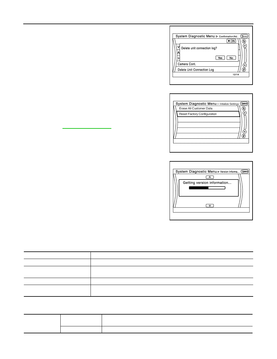
Deletes any unit connection records and error records from the AV

control unit memory. (Clear the records of the unit that has been

removed.)

Initialize Settings

“Erase All Customer Data” and “Reset Factory Configuration” are

possible.

CAUTION:

• Never perform Reset Factory Configuration except when con-

figuration is unsuccessful. 

• Factory Configuration Initialize requires configuration. For

details, refer to 

AV-525, "Description"

.

Version Information

Version information of the AV control unit is displayed.

CONSULT Function (MULTI AV)

INFOID:0000000009471443

APPLICATION ITEMS

CONSULT performs the following functions via the communication with the AV control unit.

AV Communication

When “AV communication” of “CAN Diag Support Monitor” is selected, the following function will be performed.

ECU IDENTIFICATION

JSNIA2189ZZ

AWNIA2039GB

NNNIA0181ZZ

Diagnosis mode

Description

Ecu Identification

The part number of AV control unit can be checked.

Self Diagnostic Result

Performs a diagnosis on the AV control unit and a connection diagnosis for the communication 
circuit of the Multi AV system, and displays the current and past malfunctions collectively.

Data Monitor

The diagnosis of vehicle signal that is input to the AV control unit can be performed.

Configuration

• Read and save the vehicle specification.
• Write the vehicle specification when replacing AV control unit.

AV communication

AV&NAVI C/U

Displays the communication status from AV control unit to each unit as well as the error 
counter.

AUDIO

Displays the AV control unit communication status and the error counter.

AV

DIAGNOSIS SYSTEM (AV CONTROL UNIT)

AV-537

< SYSTEM DESCRIPTION >

[COLOR DISPLAY - W/BOSE & NAVI]

C

D

E

F

G

H

I

J

K

L

M

B

A

O

P

The part number of AV control unit is displayed.

SELF DIAGNOSIS RESULT

• In CONSULT self-diagnosis, self-diagnosis results and error history are displayed collectively.

• The current malfunction indicates “CRNT”. The past malfunction indicates “PAST”.

• The timing is displayed as “0” if any of the error codes [U1000], [U1010], [U1300] and [U1310] is detected.

The counter increases by 1 if the condition is normal at the next ignition switch ON cycle.

Self-diagnosis Results Display Item

Error item

Description

Possible malfunction factor/Action to take

CAN COMM CIRCUIT [U1000]

CAN communication malfunction is detect-
ed.

Perform diagnosis with CONSULT, and 
then repair the malfunctioning parts ac-
cording to the diagnosis results.
Refer to 

AV-540, "Diagnosis Procedure"

CONTROL UNIT (CAN) [U1010]

CAN initial diagnosis malfunction is detect-
ed.

Replace the AV control unit if the malfunc-
tion occurs constantly.

CONTROL UNIT (AV) [U1310]

AV communication circuit initial diagnosis 
malfunction is detected.

Cont Unit [U1200]

AV control unit malfunction is detected.

GYRO NO CONN [U1201]

G-SENSOR NO CONN [U1202]

CAN CONT [U1216]

BLUETOOTH MODULE [U1217]

SUB CPU CONN [U1228]

iPod CERTIFICATION [U1229]

Built-in AUDIO CONN [U122E]

HDD CONN [U1218]

AV control unit malfunction is detected.

• If the hard disk drive (HDD) is function-

ing normally, there is a possibility of a 
temporary malfunction.

• Replace the AV control unit if the mal-

function occurs constantly.

HDD READ [U1219]

HDD WRITE [U121A]

HDD COMM [U121B]

HDD ACCESS [U121C]

GPS COMM [U1204]

GPS malfunction is detected.

An intermittent error caused by strong ra-
dio interference may be detected unless 
any symptom (GPS reception error, etc.) 
occurs.
Replace the AV control unit if the malfunc-
tion occurs constantly.

GPS ROM [U1205]

GPS RAM [U1206]

GPS RTC [U1207]

USB CONTROLLER [U1225]

USB connection malfunction is detected.

Check that the connection to the USB con-
nector is normal.

DSP CONN [U121D]

AV control unit malfunction is detected.

• If a disc can be played, then there is a 

possibility of the detection of a tempo-
rary malfunction.

• Replace the AV control unit if the mal-

function occurs constantly.

DSP COMM [U121E]

DVD COMM [U1227]

AV control unit malfunction is detected.

• If DVD can be played, then there is a 

possibility of the detection of a tempo-
rary malfunction.

• Replace the AV control unit if the mal-

function occurs constantly.

CONFIG UNFINISH [U122A]

The writing of configuration data is incom-
plete.

Write configuration data with CONSULT.

ST ANGLE SEN CALIB [U1232]

Predictive course line center position ad-
justment of the steering angle sensor is in-
complete.

Adjust the predictive course line center po-
sition of the steering angle sensor.

AV-538

< SYSTEM DESCRIPTION >

[COLOR DISPLAY - W/BOSE & NAVI]

DIAGNOSIS SYSTEM (AV CONTROL UNIT)

DATA MONITOR

ALL SIGNALS

• Displays the status of the following vehicle signals inputted into the AV control unit.

• For each signal, actual signal can be compared with the condition recognized on the system.

SELECTION FROM MENU

Allows the technician to select which vehicle signals should be displayed and displays the status of the

selected vehicle signals.

FRONT DISP CONN [U1243]

When either one of the following items are 
detected:
• Display unit power supply and ground 

circuits malfunction is detected.

• Communication circuits between AV 

control unit and display unit.

• Display unit power supply and ground 

circuits.

• Communication circuits between AV 

control unit and AV display unit.

GPS ANTENNA CONN [U1244]

GPS antenna connection malfunction is 
detected.

Check the connection of the GPS antenna 
connector.

USB OVERCURRENT [U1263]

Detection of over current in USB connect-
er.

Check USB harness between the AV con-
trol unit and USB connector.

• AV COMM CIRCUIT [U1300]
• SWITCH CONN [U1240]

When either one of the following items are 
detected:
• Multifunction switch power supply and 

ground circuits are malfunctioning.

• AV communication circuits between AV 

control unit and multifunction switch are 
malfunctioning.

• Multifunction switch power supply and 

ground circuits.

• AV communication circuits between AV 

control unit and multifunction switch.

Error item

Description

Possible malfunction factor/Action to take

Display Item

Display

Vehicle status

Remarks

VHCL SPD SIG

On

Vehicle speed >0 km/h (0 MPH)

Changes in indication may be delayed. This is 
normal.

Off

Vehicle speed =0 km/h (0 MPH)

PKB SIG

On

Parking brake is applied.

Off

Parking brake is released.

ILLUM SIG

On

Block the light beam from the auto 
light optical sensor when the light 
SW is ON.

Off

Expose the auto light optical sensor 
to light when the light SW is OFF or 
ON.

IGN SIG

On

Ignition switch ON

Off

Ignition switch in ACC position

REV SIG

On

Selector lever in R position

Changes in indication may be delayed. This is 
normal.

Off

Selector lever in any position other 
than R

SIDE VIEW SW

Off

This item is displayed, but cannot be 
monitored.

ROOM LAMP

Off

This item is displayed, but not used.

AV

DIAGNOSIS SYSTEM (AV CONTROL UNIT)

AV-539

< SYSTEM DESCRIPTION >

[COLOR DISPLAY - W/BOSE & NAVI]

C

D

E

F

G

H

I

J

K

L

M

B

A

O

P

WORK SUPPORT

CONFIGURATION

Configuration has three functions as follows.

Item to be selected

Description

VHCL SPD SIG

The same as when “ALL SIGNALS” is selected.

PKB SIG

ILLUM SIG

IGN SIG

REV SIG

SIDE VIEW SW

ROOM LAMP

Conditions

Description

ST ANGLE SENSOR ADJUSTMENT

Steering angle sensor neutral position adjustment can be per-
formed. Refer to 

BRC-6, "ADJUSTMENT OF STEERING ANGLE 

SENSOR NEUTRAL POSITION : Description"

.

Function

Description

READ CONFIGURATION

• Reads the vehicle configuration of current AV control unit.
• Saves the read vehicle configuration.

WRITE CONFIGURATION-Manual selection

Writes the vehicle configuration with manual selection.

WRITE CONFIGURATION-Config file

Writes the vehicle configuration with saved data.


Content   ..  177  178  179  180   ..