Nissan Maxima. Manual - part 155


  Index      Nissan     Nissan Maxima (2009-2014 year) - Service and Repair Manual


Search            


Content   ..  153  154  155  156   ..


Nissan Maxima. Manual - part 155


AV-440

< ECU DIAGNOSIS INFORMATION >

[COLOR DISPLAY - W/ BOSE]

DISPLAY UNIT

9

(B)

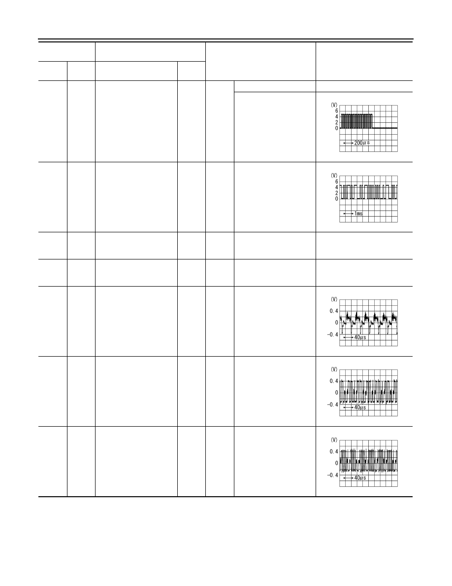
Ground RGB area (YS) signal

Input

Ignition 

switch 

ON

At RGB image displayed

5V

At rear view camera image 
displayed

11

(Y)

Ground

Communication signal
(CONT

→DISP)

Input

Ignition 

switch 

ON

When adjusting display 
brightness

13

(BR)

Ground Inverter ground

Ignition 

switch 

ON

0V

14

(LG)

Ground Signal ground

Ignition 

switch 

ON

0V

15

(W)

Ground AUX image signal

Input

Ignition 

switch 

ON

When AUX mode is select-
ed

17

(B)

Ground RGB signal (R: red)

Input

Ignition 

switch 

ON

Start confirmation/adjust-
ment mode, and then dis-
play color bar by selecting 
“Color Spectrum Bar” on 
DISPLAY DIAGNOSIS 
screen.

18

(W)

Ground RGB signal (B: blue)

Input

Ignition 

switch 

ON

Start confirmation/adjust-
ment mode, and then dis-
play color bar by selecting 
“Color Spectrum Bar” on 
DISPLAY DIAGNOSIS 
screen.

Terminal

(Wire color)

Description

Condition

Reference value

(Approx.)

+

Signal name

Input/

Output

PKIB4948J

PKIB5039J

SKIB2251J

SKIB2238J

SKIB2237J

AV

DISPLAY UNIT

AV-441

< ECU DIAGNOSIS INFORMATION >

[COLOR DISPLAY - W/ BOSE]

C

D

E

F

G

H

I

J

K

L

M

B

A

O

P

19

(G)

Ground RGB synchronizing signal

Input

Ignition 

switch 

ON

20

(W)

Ground

Vertical synchronizing (VP) 
signal

Output

Ignition 

switch 

On

21

Shield

22

(BR)

Ground

Communication signal
(DISP

→CONT)

Output

Ignition 

switch 

ON

When adjusting display 
brightness

23

Shield

Terminal

(Wire color)

Description

Condition

Reference value

(Approx.)

+

Signal name

Input/

Output

SKIB3603E

SKIB3598E

PKIB5039J

AV-442

< ECU DIAGNOSIS INFORMATION >

[COLOR DISPLAY - W/ BOSE]

BOSE SPEAKER AMP

BOSE SPEAKER AMP

Reference Value

INFOID:0000000009471387

TERMINAL LAYOUT

PHYSICAL VALUES

ALNIA1165ZZ

Terminal

(Wire color)

Description

Condition

Reference value

(Approx.)

+

Signal name

Input/

Output

1

(LG)

2

(V)

Audio signal tweeter LH

Output

Ignition 

switch 

ON

Audio output

4

(G)

3

(W)

Audio signal tweeter RH

Output

Ignition 

switch 

ON

Audio output

5

(R)

6

(BR)

Audio signal subwoofer RH

Output

Ignition 

switch 

ON

Audio output

7

(B)

Ground Ground

Ignition 

switch 

ON 

0V

10

(SB)

Ground Battery power supply

Input

Ignition 

switch 

OFF

Battery voltage

11

(GR)

Ground Battery power supply

Input

Ignition 

switch 

OFF

Battery voltage

12

(B)

Ground Ground

Ignition 

switch 

ON 

0V

SKIB3609E

SKIB3609E

SKIB3609E

AV

BOSE SPEAKER AMP

AV-443

< ECU DIAGNOSIS INFORMATION >

[COLOR DISPLAY - W/ BOSE]

C

D

E

F

G

H

I

J

K

L

M

B

A

O

P

13

(L)

8

(P)

Audio signal subwoofer LH

Output

Ignition 

switch 

ON

Audio output

14

(LG)

9

(O)

Audio signal rear door RH

Output

Ignition 

switch 

ON

Audio input

18

(W)

19

(B)

Audio signal rear door RH

Output

Ignition 

switch 

ON

Audio input

20

(SB)

Ground Amp. ON signal

Input

Ignition 

switch 

ACC

Battery voltage

24

(GR)

23

(L)

Audio signal rear LH

Input

Ignition 

switch 

ON

Audio input

26

(BR)

25

(L)

Audio signal rear RH

Input

Ignition 

switch 

ON

Audio input

28

(G)

15

(L)

Audio signal rear door LH

Output

Ignition 

switch 

ON

Audio output

Terminal

(Wire color)

Description

Condition

Reference value

(Approx.)

+

Signal name

Input/

Output

SKIB3609E

SKIB3609E

SKIB3609E

SKIB3609E

SKIB3609E

SKIB3609E


Content   ..  153  154  155  156   ..