Nissan Maxima. Manual - part 154
AV-436
< ECU DIAGNOSIS INFORMATION >
[COLOR DISPLAY - W/ BOSE]
AV CONTROL UNIT
95
(B)
97
(R)
AUX audio signal RH
Input
Ignition
switch
ON
When AUX mode is select-
ed
96
(W)
97
(R)
AUX audio signal LH
Input
Ignition
switch
ON
When AUX mode is select-
ed
103
(SB)
Ground CD eject signal
Input
—
Pressing the eject switch
0V
Except for above
3.3V
104
(G)
Ground Ignition signal
Input
Ignition
switch
ON
—
Battery voltage
105
(P/B)
Ground Reverse signal
Input
Ignition
switch
ON
R position
Battery voltage
Other than R position
0V
106
(G/R)
Ground Parking brake signal
Input
Ignition
switch
ON
Parking brake ON
0V
Parking brake OFF
Battery voltage
107
(V/W)
Ground
Vehicle speed signal
(8-pulse)
Input
Ignition
switch
ON
When vehicle speed is ap-
prox. 25 MPH (40 km/h)
108
(V)
114
(LG)
Rear RH pre-amp. sound
signal
Output
Ignition
switch
ON
Audio output
109
(B)
115
(W)
Front RH pre-amp. sound
signal
Output
Ignition
switch
ON
Audio output
110
(B/P)
Ground Amp. ON signal
Output
Ignition
switch
ON
Battery voltage
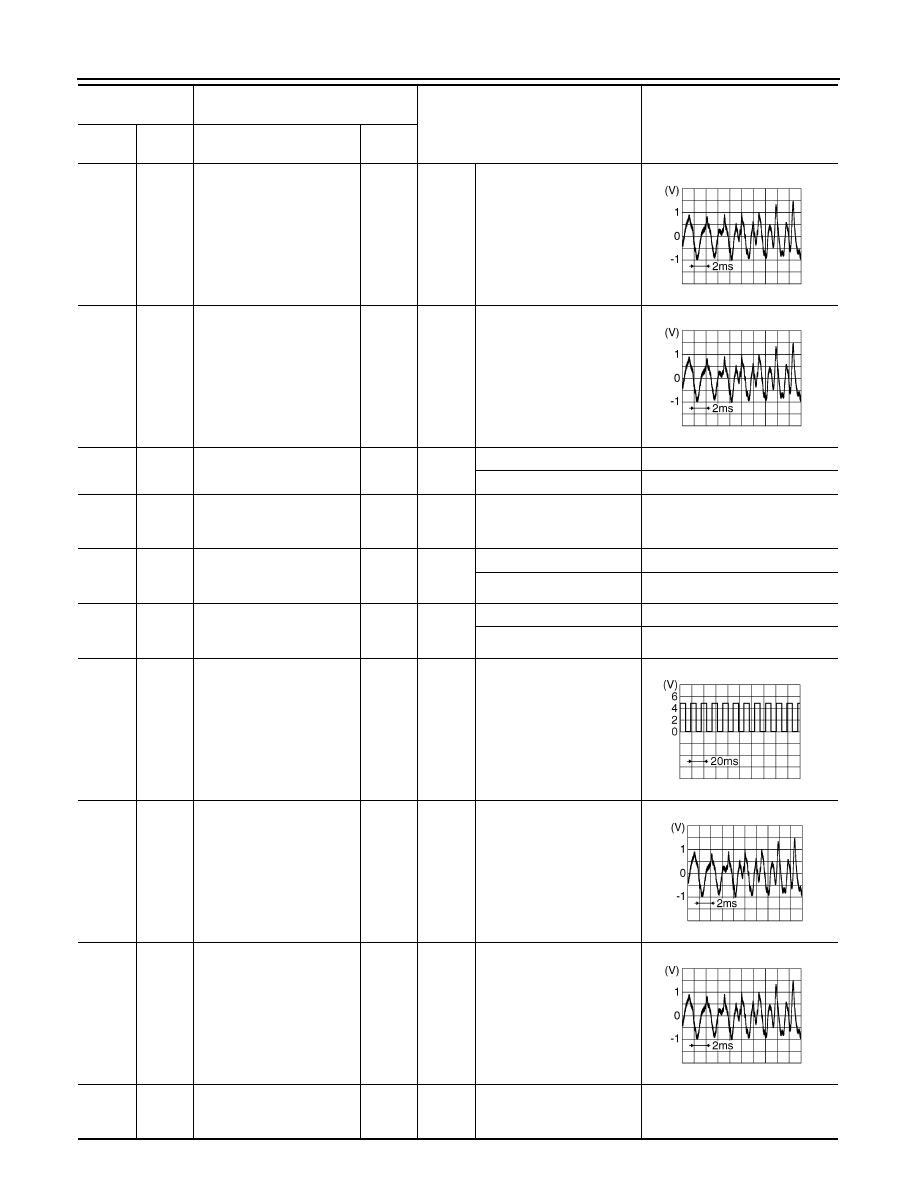
Terminal
(Wire color)
Description
Condition
Reference value
(Approx.)
+
–
Signal name
Input/
Output
SKIB3609E
SKIB3609E
SKIA6649J
SKIB3609E
SKIB3609E