Nissan Maxima. Manual - part 151
AV-424
< DTC/CIRCUIT DIAGNOSIS >
[COLOR DISPLAY - W/ BOSE]
COMMUNICATION SIGNAL CIRCUIT
COMMUNICATION SIGNAL CIRCUIT
SATELLITE RADIO TUNER
SATELLITE RADIO TUNER : Description
INFOID:0000000009471378
Communication signals are exchanged between the AV control unit and satellite radio tuner using the commu-
nication circuits.
SATELLITE RADIO TUNER : Diagnosis Procedure
INFOID:0000000009471379
Regarding Wiring Diagram information, refer to
AV-449, "Wiring Diagram - With BOSE Audio system Without
1.
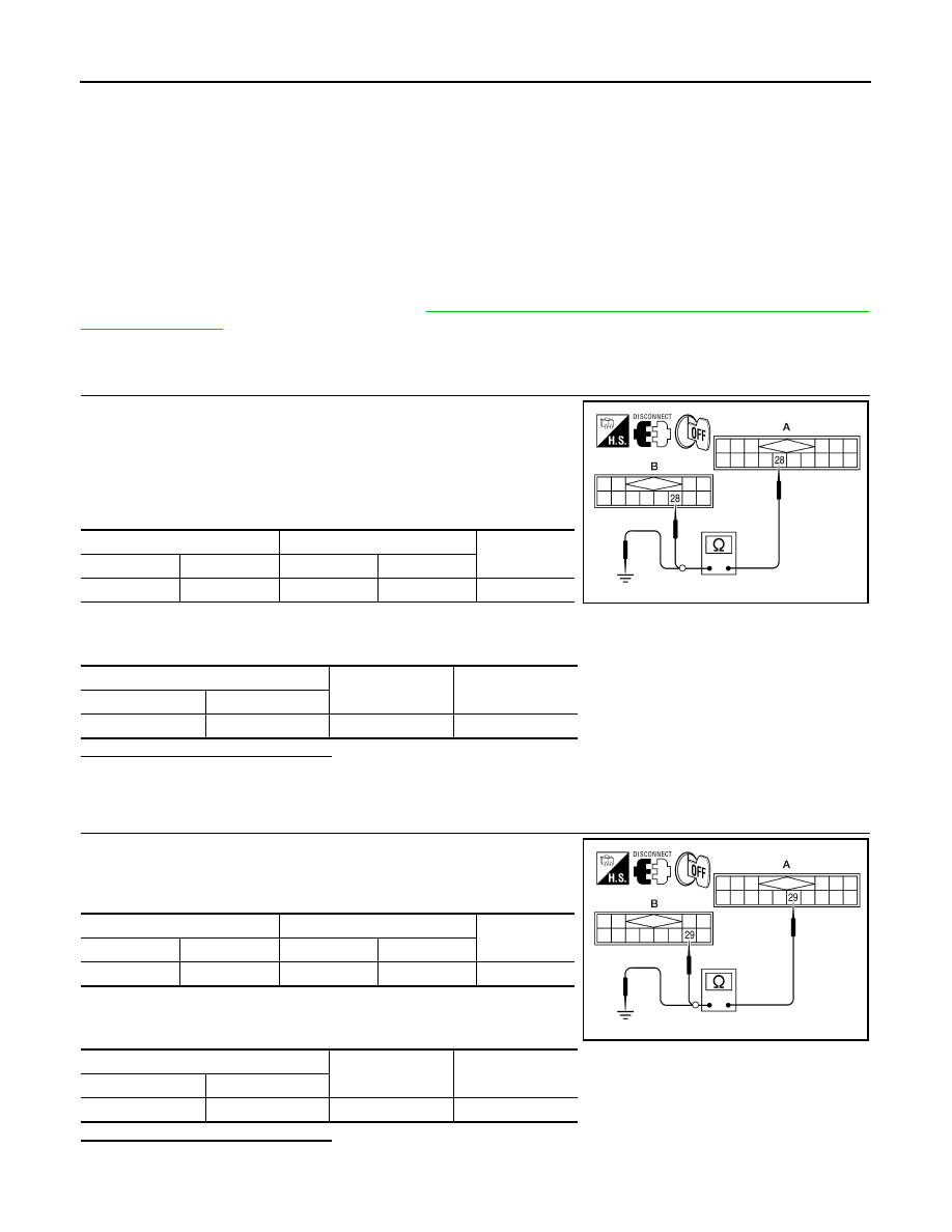
CHECK HARNESS - 1
1. Turn ignition switch OFF.
2. Disconnect satellite radio tuner (factory installed) connector
B111 and AV control unit connector M153.
3. Check continuity between satellite radio tuner (factory installed)
harness connector B111 (A) terminal 28 and AV control unit har-
ness connector M153 (B) terminal 28.
4. Check continuity between satellite radio tuner (factory installed)
harness connector B111 (A) terminal 28 and ground.
Are continuity results as specified?
YES
>> GO TO 2.
NO
>> Repair harness or connector.
2.
CHECK HARNESS - 2
1. Check continuity between satellite radio tuner (factory installed)
harness connector B111 (A) terminal 29 and AV control unit har-
ness connector M153 (B) terminal 29.
2. Check continuity between satellite radio tuner (factory installed)
harness connector B111 (A) terminal 29 and ground.
Are continuity results as specified?
YES
>> GO TO 3.
NO
>> Repair harness or connector.
A
B
Continuity
Connector
Terminal
Connector
Terminal
B111
28
M153
28
Yes
A
—
Continuity
Connector
Terminal
B111
28
Ground
No
ALNIA0334GB
A
B
Continuity
Connector
Terminal
Connector
Terminal
B111
29
M153
29
Yes
A
—
Continuity
Connector
Terminal
B111
29
Ground
No
ALNIA0657GB