Nissan Maxima. Manual - part 149


  Index      Nissan     Nissan Maxima (2009-2014 year) - Service and Repair Manual


Search            


Content   ..  147  148  149  150   ..


Nissan Maxima. Manual - part 149


AV-416

< DTC/CIRCUIT DIAGNOSIS >

[COLOR DISPLAY - W/ BOSE]

REAR DOOR SPEAKER

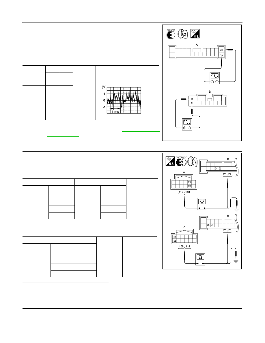
1. Connect BOSE speaker amp. connectors and suspect speaker

connector.

2. Turn ignition switch to ACC.

3. Push POWER switch.

4. Check the signal between BOSE speaker amp. harness connec-

tors B109 (A) and B110 (B) terminals with CONSULT or oscillo-

scope.

Are audio signal voltage readings as specified?

YES

>> Replace suspect speaker. Refer to 

AV-491, "Removal

and Installation"

.

NO

>> GO TO 4.

4.

HARNESS CHECK

1. Disconnect AV control unit connector M157 and BOSE speaker

amp. connector B109.

2. Check continuity between AV control unit harness connector

M157 (A) and BOSE speaker amp. harness connector B109 (B).

3. Check continuity between AV control unit harness connector

M157 (A) and ground.

Are the continuity test results as specified?

YES

>> GO TO 5.

NO

>> • Check connector housings for disconnected or loose terminals.

• Repair harness or connector.

5.

REAR DOOR SPEAKER SIGNAL CHECK

Connector

Terminals

Condition

Reference

signal

(+)

(-)

A: B109

28

15

Receive 
audio sig-
nal

B: B110

14

9

AWNIA1703ZZ

SKIA0177E

A

Continuity

Connector

Terminal

Connector

Terminal

M157

112

B109

24

Yes

118

23

108

26

114

25

A

Continuity

Connector

Terminal

M157

112

Ground

No

118

108

114

AWNIA1762ZZ

AV

REAR DOOR SPEAKER

AV-417

< DTC/CIRCUIT DIAGNOSIS >

[COLOR DISPLAY - W/ BOSE]

C

D

E

F

G

H

I

J

K

L

M

B

A

O

P

1. Connect AV control unit connector M157 and BOSE speaker

amp. connector B109.

2. Turn ignition switch to ACC.

3. Push POWER switch.

4. Check the signal between AV control unit harness connector ter-

minals with CONSULT or oscilloscope.

Is the audio signal voltage reading as specified?

YES

>> Replace BOSE speaker amp. Refer to 

AV-493,

"Removal and Installation"

.

NO

>> Replace AV control unit. Refer to 

AV-481, "Removal and

Installation"

.

Connector

Terminals

Condition

Reference

signal

(+)

(-)

M157

112

118

Receive 
audio sig-
nal

108

114

ALNIA1176ZZ

SKIA0177E

AV-418

< DTC/CIRCUIT DIAGNOSIS >

[COLOR DISPLAY - W/ BOSE]

SUBWOOFER

SUBWOOFER

Description

INFOID:0000000009471372

The AV control unit sends audio signals to the BOSE speaker amp. The BOSE speaker amp. amplifies the

audio signals before sending them to the subwoofers using the audio signal circuits.

Diagnosis Procedure

INFOID:0000000009471373

Regarding Wiring Diagram information, refer to 

AV-449, "Wiring Diagram - With BOSE Audio system Without

Navigation System"

.

1.

CONNECTOR CHECK

Check the AV control unit, BOSE speaker amp. and subwoofer connectors for the following:

•  Proper connection

•  Damage

•  Disconnected or loose terminals
Is the inspection result normal?

YES

>> GO TO 2

NO

>> Repair the terminal and connector.

2.

HARNESS CHECK

1. Disconnect BOSE speaker amp. connector B110 and suspect

rear subwoofer connector.

2. Check continuity between BOSE speaker amp. harness connec-

tor B110 (A) and suspect rear subwoofer harness connector (B).

3. Check continuity between BOSE speaker amp. harness connec-

tor B110 (A) and ground.

Are the continuity test results as specified?

YES

>> GO TO 3.

NO

>> • Check connector housings for disconnected or loose terminals.

• Repair harness or connector.

3.

REAR SUBWOOFER SIGNAL CHECK

A B 

Continuity

Connector

Terminal

Connector

Terminal

B110

13

B106

1

Yes

8

2

5

B107

1

6

2

A

Continuity

Connector

Terminal

B110

13

Ground

No

8

5

6

AWNIA1705ZZ

AV

SUBWOOFER

AV-419

< DTC/CIRCUIT DIAGNOSIS >

[COLOR DISPLAY - W/ BOSE]

C

D

E

F

G

H

I

J

K

L

M

B

A

O

P

1. Connect BOSE speaker amp. connector B110 and suspect rear

subwoofer connector.

2. Turn ignition switch to ACC.

3. Push POWER switch.

4. Check the signal between BOSE speaker amp. harness connec-

tor B110 terminals with CONSULT or oscilloscope.

Is the audio signal voltage as specified?

YES

>> Replace suspect rear subwoofer. Refer to 

AV-492,

"Removal and Installation"

.

NO

>> GO TO 4.

4.

HARNESS CHECK

1. Disconnect AV control unit connector M157 and BOSE speaker

amp. connector B109.

2. Check continuity between AV control unit harness connector

M157 (A) and BOSE speaker amp. harness connector B109 (B).

3. Check continuity between AV control unit harness connector

M157 (A) terminal and ground.

Are continuity test results as specified?

YES

>> GO TO 5.

NO

>> • Check connector housings for disconnected or loose terminals.

• Repair harness or connector.

5.

REAR SUBWOOFER SIGNAL CHECK

Connector

Terminals

Condition

Reference

signal

(+)

(-)

B110

13

8

Receive au-
dio signal

5

6

AWNIA1706ZZ

SKIA0177E

A

Continuity

Connector

Terminal

Connector

Terminal

M157

112

B109

24

Yes

118

23

108

26

114

25

A

Continuity

Connector

Terminal

M157

112

Ground

No

118

108

114

AWNIA1762ZZ


Content   ..  147  148  149  150   ..